453
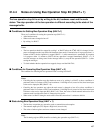
21.4.1 Configuration of Control Status Register (CSR)
This register indicates bus operation, node status, transmit output enable and transmit/
receive status. The lower 8-bit with the control status register (CSR) is prohibited from
executing any bit manipulation instructions (Read-Modify-Write instructions). Only in
the case of HALT bits unchanged (initialization of the macro instructions etc.), there is
no problem even if any bit manipulation instructions is used.
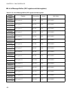
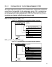
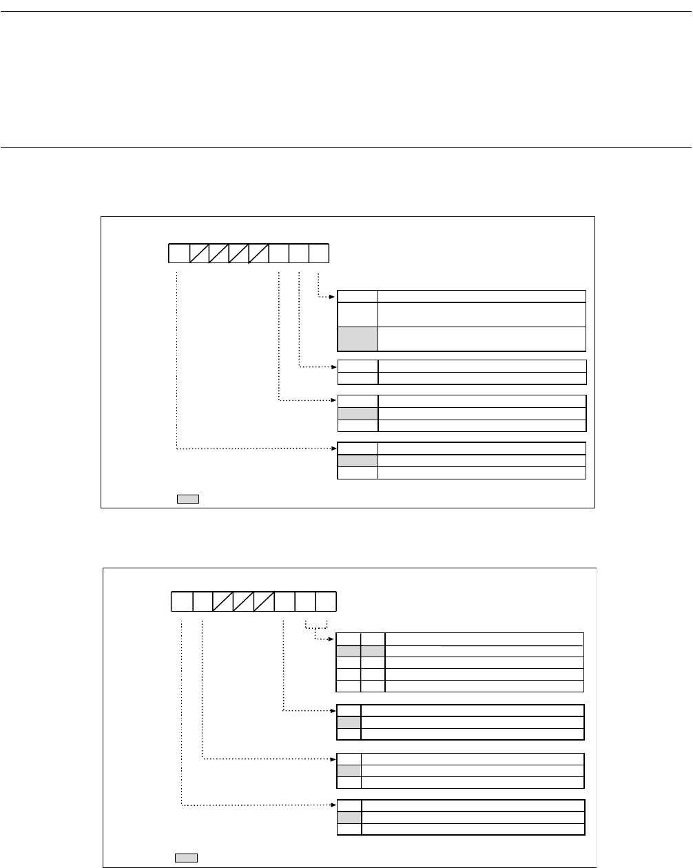
■ Control Status Register (CSR) (Lower)
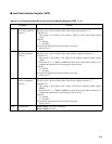
Figure 21.4-1 Configuration of the Control Status Register (lower byte)
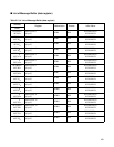
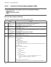
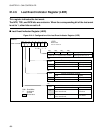
■ Control Status Register (CSR) (upper)
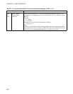
Figure 21.4-2 Configuration of the Control Status Register (upper byte)
Reset Vaue
0XXXX0X1
B
45321
7
6
0
R/WWR/W---R/W
bit7
bit1
-
- : Unused
X : Undefined
W : Write only
R/W : Read/Writ
: Reset value
Always write "0" to this bit.
NIE
0
1
Node status transition interrupt enable
Node status transition interrupt enabled
Node status transition interrupt disabled
TOE
0
1
Transmit output enable
General-purpose port pin
Transmit pin of TX
HALT
0
1
Bus operation styop bit
Write: Stop of bus operation is released.
Read:The state of bus operation is not stop mode
Write: Stops bus operation
Read: Bus operation in stop mode
bit0
Reserved
0
Reserved bit
bit2
Address:
CSR1 (Lower)
CAN1: 007D00
H
TOE NIE
Re-
served
HALT
Reset value
00XXX000
B
1213 11 10 9
15
14
8
RRR/W---R
RS
Reception status bit
Message is not received.
Massage is being received.
bit14
0
1
TS
Transfer status bit
Message is not transferred.
Message is being transferred.
bit15
0
1
Node status bit
NS1
Error active
Warning (error active)
bit9
0
0
1
1
NS0
bit8
0
1
0
1
NT
Node status transfer flag
With node status transfer
Without node status reansfer
bit10
0
1
R
Error passive
Bus off
- : Unused
X : Undefined
R : Read only
R/W : Read/Write
: Reset value
Address:
CSR1 (High)
CAN1: 007D01
H
TS RS NT NS1 NS0


