650
INDEX
Index
Numerics
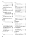
16-bit Free-run Timer
Block Diagram of 16-bit Free-run Timer ............213
Explanation of Operation of 16-bit Free-run Timer
..........................................................229
16-bit I/O Timer
16-bit I/O Timer Interrupt and EI
2
OS.................228
Block Diagram of 16-bit I/O Timer....................211
Functions of 16-bit I/O Timer............................210
Generation of Interrupt Request from 16-bit I/O Timer
..........................................................216
Interrupts of 16-bit I/O Timer............................227
Module Configuration of 16-bit I/O Timer..........210
Pins of 16-bit I/O Timer....................................216
Precautions when Using 16-bit I/O Timer...........233
Program Example of 16-bit I/O Timer................234
16-bit PPG Output Operation Mode
Setting for 16-bit PPG Output Operation Mode
..........................................................304
16-bit Reload Registers
16-bit Reload Registers (TMRLR) .....................250
16-bit Reload Timer
16-bit Reload Timer Registers and Reset Value
..........................................................243
Block Diagram of 16-bit Reload Timer...............240
Correspondence between 16-bit Reload Timer
Interrupt and EI
2
OS.............................251
EI
2
OS Function of 16-bit Reload Timer..............251
Generation of Interrupt Request from 16-bit
Reload Timer......................................244
Interrupts of 16-bit Reload Timer.......................251
Operation Modes of 16-bit Reload Timer............238
Pins of 16-bit Reload Timer ..............................242
Precautions when Using 16-bit Reload Timer......262
Setting of 16-bit Reload Timer ..........................252
16-bit Timer Register
16-bit Timer Registers (TMR)...........................249
Operating State of 16-bit Timer Register ............253
Operation as 16-bit Timer Register Underflows
..................................................255, 260
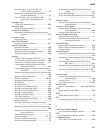
24-bit Operand
24-bit Operand Specification............................... 33
512K-bit Flash Memory
512K-bit Flash Memory Features ...................... 530
Sector Configuration of the 512K-bit Flash Memory
......................................................... 531
8+8-bit PPG
Setting for 8+8-bit PPG Output Operation Mode
......................................................... 307
8-/10-bit A/D Converter
8-/10-bit A/D Converter Interrupt and EI
2
OS...... 358
A/D-converted Data Protection Function in
8-/10-bit A/D Converter....................... 367
Block Diagram of 8-/10-bit A/D Converter......... 341
Conversion Modes of 8-/10-bit A/D Converter
......................................................... 340
EI
2
OS Function of 8-/10-bit A/D Converter........ 358
Function of 8-/10-bit A/D Converter.................. 340
Generation of Interrupt from 8-/10-bit A/D Converter
......................................................... 345
List of Registers and Reset Values of 8-/10-bit
A/D Converter.................................... 345
Pins of 8-/10-bit A/D Converter ........................ 344
Precautions when Using 8-/10-bit A/D Converter
......................................................... 369
8-/16-bit PPG Timer
Block Diagram of 8-/16-bit PPG Timer C .......... 286
Block Diagram of 8-/16-bit PPG Timer D .......... 288
Functions of 8-/16-bit PPG Timer...................... 282
Generation of Interrupt Request from 8-/16-bit
PPG Timer ......................................... 291
Interrupt of 8-/16-bit PPG Timer ....................... 299
List of Registers and Reset Values of 8-/16-bit
PPG Timer ......................................... 291
Operation Modes of 8-/16-bit PPG Timer........... 283
Operation of 8-/16-bit PPG Timer ..................... 300
Pins of 8-/16-bit PPG Timer.............................. 290
Precautions when Using 8-/16-bit PPG Timer..... 310
8-bit PPG Output 2-channel Independent Operation
Mode
Setting for 8-bit PPG Output 2-channel
Independent Operation Mode ............... 301


