


384
CHAPTER 20 LIN-UART
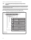
■ LIN-UART operation modes
The LIN-UART operates in four different modes, which are determined by the MD0- and the MD1-bit of
the serial mode register (SMR). Mode 0 and 2 are used for bidirectional serial communication, mode 1 for
master/slave communication and mode 3 for LIN master/slave communication.
The MD1 and MD0 bits of the serial mode register (SMR) determine the operation mode of LIN-UART as
shown in the following table:
Note:
Mode 1 operation is supported both for master or slave operation of LIN-UART in a master-slave
connection system. In Mode 3 the LIN-UART function is locked to 8N1-Format, LSB first.
If the mode is changed, LIN-UART cuts off all possible transmission or reception and awaits then new
action.
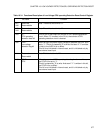
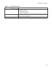
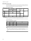
Table 20.1-2 Operation Mode of LIN-UART
Operation Mode Data Length Synchronous/
Asynchronous
Length of
Stop Bit
Data Bit Format
No Parity With Parity
0 Normal mode 7 or 8 bits Asynchronous 1 bit or 2 bits LSB first
MSB first
1 Multiprocessor
mode
7 or 8 bits-+1 * - Asynchronous
2 Normal mode 8 Synchronous None,
1 bit,
2 bits
3 LIN mode 8 - Asynchronous 1 bit LSB first
- : Setting disabled
*: +1 is the address/data select bit (A/D) used for controlling communication in multiprocessor mode.
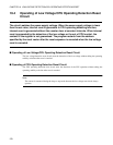
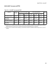
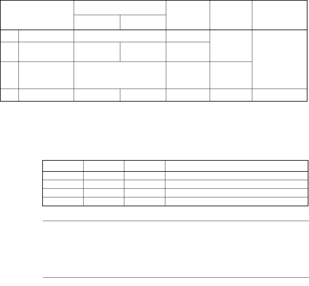
Table 20.1-3 Operation Mode of LIN-UART
MD1 MD0 Mode Type
000Asynchronous (normal mode)
011Asynchronous (multiprocessor mode)
102Synchronous (normal mode)
113Asynchronous (LIN mode)