310
CHAPTER 16 8-/16-BIT PPG TIMER
16.6 Precautions when Using 8-/16-bit PPG Timer
This section explains the precautions when using the 8-/16-bit PPG timer.
■ Precautions when Using 8-/16-bit PPG Timer
●
Effect on 8-/16-bit PPG timer when using timebase timer output
• If the output signal of the timebase timer is used as the input signal for the count clock of the 8-/16-bit
PPG timer (PPGnm: PCM2 to PCM0="111
B
", PCS2 to PCS0="111
B
"), deviation may occur in the first
count cycle in which the PPG timer is started by trigger input or in the count cycle immediately after the
PPG timer is stopped.
• When the timebase timer counter is cleared (TBTC: TBR=0) during the count operation of the PPG
down counter, deviation may occur in the count cycle.
●
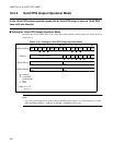
Setting of PPG reload registers when using 8-bit PPG timer
• The Low-level and High-level pulse widths are determined at the timing of reloading the values in the
Low-level PPG reload registers (PRLLn, PRLLm) to the PPG down counter.
• If the 8-bit PPG timer is used in the 8-bit PPG output 2-channel independent operation mode or the 8 +
8-bit PPG output operation mode, use a word instruction to set both High-level and Low-level PPG
reload registers (PRLLn/PRLHn, PRLLm/PRLHm) at the same time.
Using a byte instruction may cause an unexpected pulse to be generated.
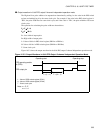
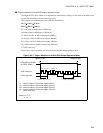
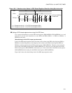
[Example of rewriting PPG reload registers using byte instruction]
Immediately before the signal level of the PPG pin switches from High to Low, if the value in the High-
level PPG reload register (PRLH) is rewritten after the value in the Low-level PPG reload register (PRLL)
is rewritten using the byte instruction, a Low-level pulse width is generated after rewriting and a High-level
pulse width is generated before rewriting.
Figure 16.6-1 shows the waveform as the values in the PPG reload registers are rewritten using the byte
instruction.
Note: n = C, E
m = n+1


