


404
CHAPTER 20 LIN-UART
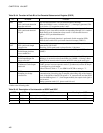
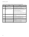
Table 20.4-6 Function of Each Bit in the Extended Communication Control Register (ECCR)
NO. Bit name Function
bit7 Unused bit This bit is unused bit. Reading bit is undefined. Always write "0".
bit6 LBR:
Lin Synch break Generating bit
Writing a 1 to this bit generates a LIN synch break of the length
selected by the LBL0/LBL1 bits of the ESCR, if operation mode 3
is selected. Setting to "0" in operation mode 0.
bit5 MS:
Master/Slave mode selection bit in
mode 2
This bit selects master or slave mode of LIN-UART in
synchronous mode 2. If master is selected LIN-UART generates
the synchronous clock by itself. If slave mode is selected, LIN-
UART receives external serial clock.
This bit is fixed to "0" in operation mode 0, 1 and 3.
Change this bit, when the SCR: TXE bit is "0".
Note:
If slave mode is selected, the clock source must be external and
enabled the external clock input (SMR: SCKE = 0, EXT = 1, OTO
= 1).
bit4 SCDE:
Serial clock delay enable bit in mode 2
If this bit is set to 1 the serial output clock is delayed as shown in
Figure 20.7-5 if LIN-UART operates in master mode 2. This bit is
enabled to SPI.
This bit is fixed to "0" in operation mode 0, 1, and 3.
bit3 SSM:
Start/Stop bit mode enable bit in mode
2
This bit adds start and stop bits to the synchronous data format in
operation mode 2. It is ignored in mode 0, 1, and 3.
This bit is fixed to "0" in operation mode 0, 1, and 3.
bit2 Unused bit Unused bit. Reading value is undefined. Always write to "0".
bit1 RBI:
Reception bus idle detection flag bit
This bit is "1" if there is no reception activity on the SINn pin and
it is kept at "H".
Do not use this bit in mode 2 when SSM=0.
bit0 TBI:
Transmission bus idle detection flag bit
This bit is "1" if there is no transmission activity on the SOTn pin.
Do not use this bit in mode 2 when SSM=0.