


561
CHAPTER 25 EXAMPLES OF MB90F362/T(S), MB90F367/T(S) SERIAL PROGRAMMING CONNECTION
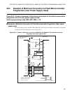
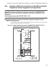
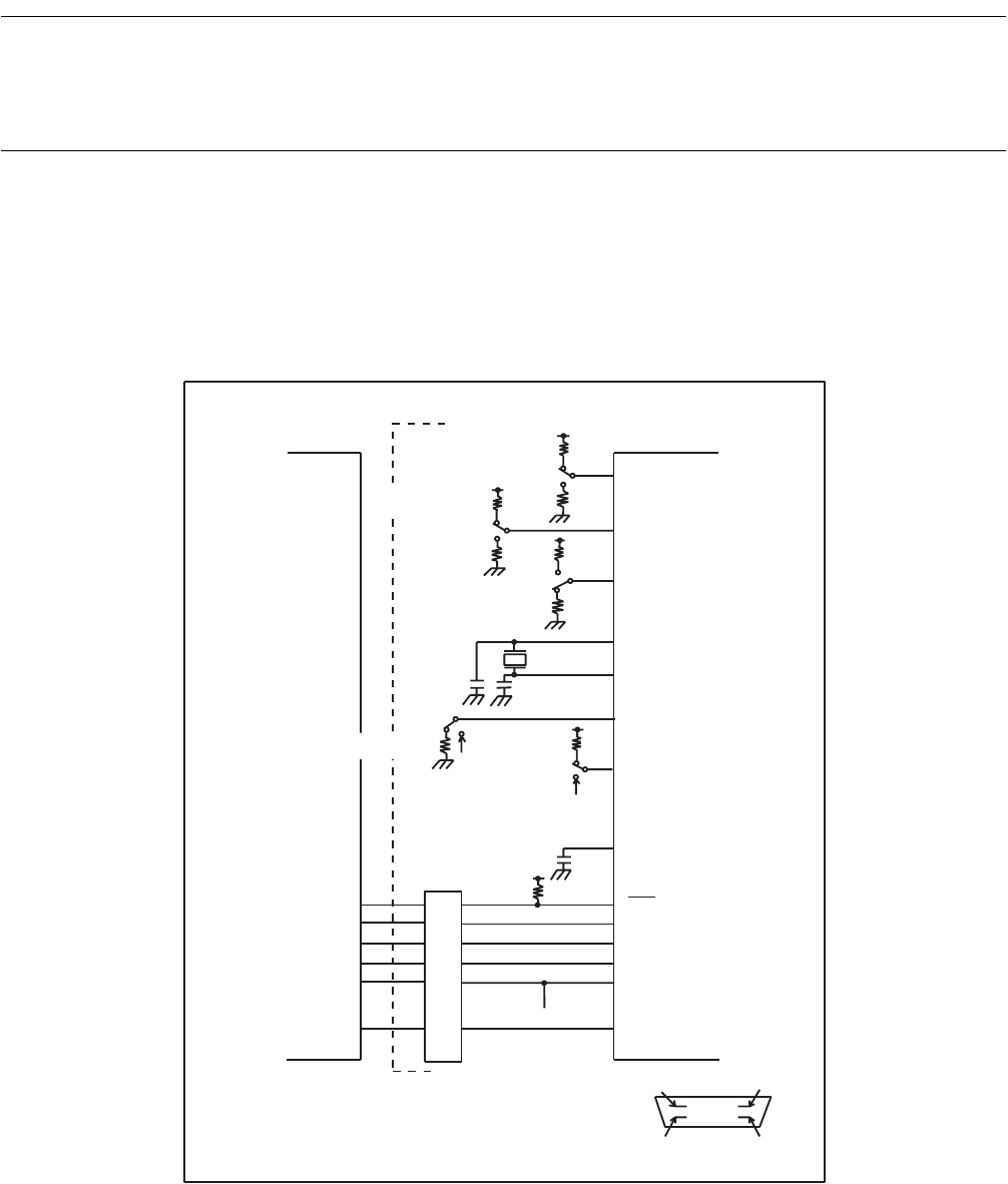
25.4 Example of Minimum Connection to Flash Microcontroller
Programmer (User Power Supply Used)
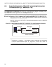
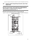
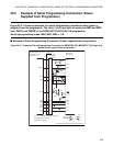
Figure 25.4-1 shows an example of the minimum connection to the flash microcontroller
programmer when the user power supply is used.
Serial reprogramming mode: MD2, MD1, MD0 = 110.
■ Example of Minimum Connection to Flash Microcontroller Programmer (User power
supply used)
For a flash memory write, the MD2, MD1, MD0, P83, and P84 pins and flash microcontroller programmer
need not be connected if the pins are set as Figure 25.4-1 .
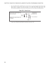
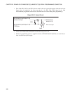
Figure 25.4-1
Example of Minimum Connection to MB90F362/T(S), MB90F367/T(S) Flash Microcontroller
Programmer (User power supply Used)
10kΩ
MD1
MD2
AF220/AF210/AF120/AF110
MD0
10k
Ω
10kΩ
10kΩ
10kΩ
10kΩ
1 for serial rewriting
0 for serial rewriting
User circuit
P83
10kΩ
P84
User circuit
1 for serial rewriting
X0
X1
4MHz
to 16MHz
Vss
GND
Connector
(7,8,
14,15,
21,22,
1,28)
SIN1
TTXD (13)
SOT1
TRXD
(27)
SCK1TCK
(6)
Vcc
(2)
TVcc
10kΩ
/TRES RST
(5)
C
0.1µF
10kΩ
DX10-28S
DX20-28S
1 for serial rewriting
0 for serial rewriting
DX10-28S
DX20-28S
MB90F362/T(S),
MB90F367/T(S)
flash microcontroller
programmer
User system
- DX10-28S : Right-angle type
- DX20-28S : Straight type
User power supply
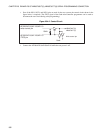
Connector (Hirose Electronics Ltd.) pin arrangement
1 pin
28 pin 15 pin
14 pin
- 3,4,9,10,11,12,16,17,18,19,20,
23,24,25 and 26 pins are OPEN.