


403
CHAPTER 20 LIN-UART
20.4.6 Extended Communication Control Register (ECCR)
The extended communication control register (ECCR) provides bus idle detection,
synchronous clock settings, and the LIN synch break generation.
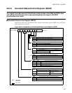
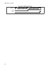
■ Extended Communication Control Register (ECCR)
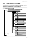
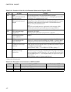
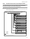
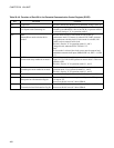
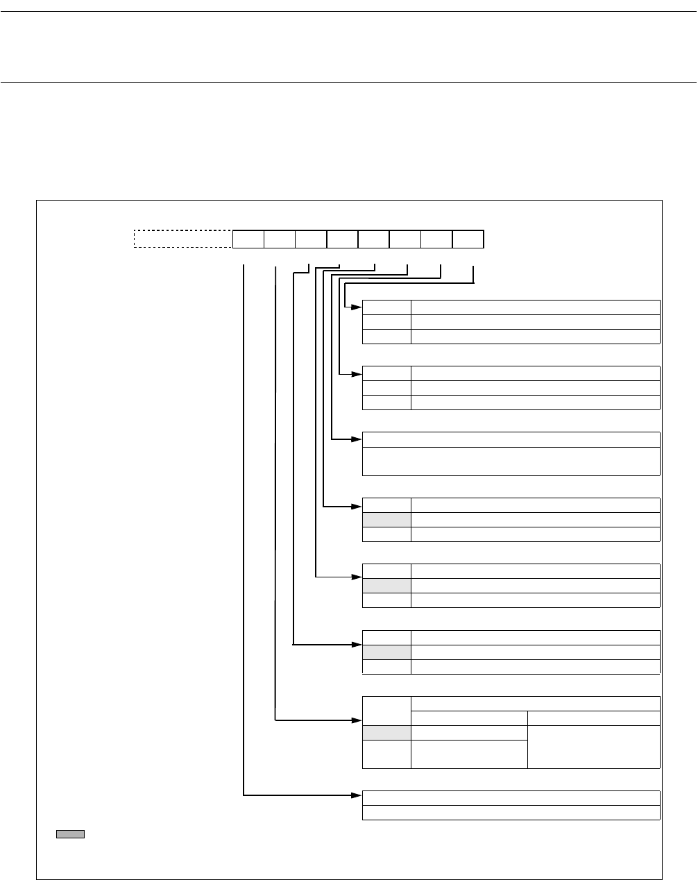
Figure 20.4-7 shows the configuration of the extended communication control register (ECCR), and Table
20.4-6 shows the function of each bit.
Figure 20.4-7 Configuration of the Extended Communication Control Register (ECCR)
MS SCDE SSM RBI TBI
000000XXB
ECCR0:000024H
ECCR1:00002CH
LBR
bit 7
bit 6 bit 5 bit 4 bit 3 bit 2 bit 1 bit 0
−
W R/W R/W R/W − RR
bit 15 bit 8
Address
Initial value
bit 0
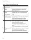
TBI* Transmission bus idle detection flag bit
0 Transmission is ongoing
1 No transmission activity
bit1
RBI* Reception bus idle detection flag bit
0 Reception is ongoing
1 No reception activity
bit 2
Unused bit
Reading value is undefined.
Always write "0".
bit 3
SSM Start/stop bit mode enable bit in mode 2
0 No start/stop bit
1 Enable start/stop bit
bit 4
SCDE Serial Clock Delay enable bit in mode 2
0 Disable clock delay
1 Enable clock delay
bit 5
MS Master/Slave mode selection bit in mode 2
0 Master mode (generating serial clock)
1 Slave mode (receiving external serial clock)
bit 6
LBR
Generating LIN synch break bit
write read
0 Ignored
Always read 0
1
Generate LIN Synch
break
bit 7
Unused bit
Read value is undefined. Always write 0
R/W : Read/Write
R : Read only
W : Write only
X : Undefined
: Initial value
*: Not used in operation mode 2 when SSM = 0