


295
CHAPTER 16 8-/16-BIT PPG TIMER
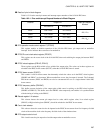
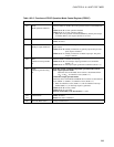
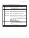
Table 16.3-3 Functions of PPGD Operation Mode Control Register (PPGCD)
Bit name Function
bit15 PEN1:
PPG1 operation enable bit
This bit enables or disables the count operation of the 8-/16-bit PPG timer D.
When set to "0": Count operation disabled
When set to "1": Count operation enabled
• When the count operation is disabled (PEN1 = 0), and the pulse output is enabled (PE1=1),
the output is held at a Low level.
bit14 Undefined bit Read: The value is undefined.
Write: No effect
bit13 PE1:
PPG1 Pin output enable bit
This bit switches between PPGD pin functions and enables or disables the pulse output.
When set to "0":
PPGD pin functions as general-purpose I/O port. The pulse output is disabled.
When set to "1": PPGD pin functions as PPGD output pin. The pulse output is enabled.
bit12 PIE1:
Underflow interrupt enable
bit
This bit enables or disables an interrupt.
When set to "0": No interrupt request is generated even at underflow (PUF1 = 1)
When set to "1": Interrupt request is generated at underflow (PUF1 = 1)
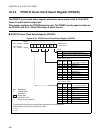
bit11 PUF1:
Underflow generation flag
bit
8-bit PPG output 2-channel independent operation mode, 8+8-bit PPG output operation
mode: When the value of the PPGD down counter is decremented from "00
H
" to "FF
H
", an
underflow occurs (PUF1 = 1).
16-bit PPG output operation mode:When the values of the PPGC and PPGD down
counters are decremented from "0000
H
" to "FFFF
H
", an
underflow occurs (PUF1 = 1).
• When an underflow occurs (PUF1 = 1) with an underflow interrupt request enabled (PIE1
= 1), an interrupt request is generated.
When set to "0": Clears counter
When set to "1": No effect
Read by read modify write instructions: 1 is read.
bit10
bit9
MD1, MD0:
Operation mode select bits
These bits set the operation mode of the 8-/16-bit PPG timer.
[Any mode other than 8-bit PPG output 2-channel independent operation mode]
• Use a word instruction to set the PPG operation enable bits (PEN0 and PEN1) at one time.
• Do not set operation of only one of the two channels (PEN1 = 0/PEN0 = 1 or PEN1 = 1/
PEN0 = 0).
Note:
Do not set the MD1 and MD0 bits to "10
B
".
bit8 Reserved: Reserved bit Always set this bit to 1.