


388
CHAPTER 20 LIN-UART
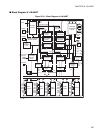
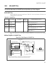
■ Explanation of the different blocks
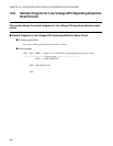
●
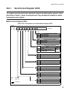
Reload Counter
The reload counter is a 15-bit reload counter that functions as the dedicated baud rate generator. It can
select external clock or internal clock for the transmitting and receiving clocks. The reload counter has a
15-bit register for the reload value. The actual count of the transmission reload counter can be read via the
BGRn0/n1.
●
Reception Control Circuit
The reception control circuit consists of a received bit counter, start bit detection circuit, and received
parity counter. The received bit counter counts reception data bits. When reception of one data item for the
specified data length is completed, the received bit counter sets the reception data register full flag. In this
case, if the reception interrupt is enabled, the reception interrupt request is generated. The start bit detection
circuit detects start bits from the serial input signal and sends a signal to the reload counter to synchronize it
to the falling edge of these start bits. The received parity counter calculates the parity of the reception data.
●
Reception Shift Register
The reception shift register fetches reception data input from the SINn pin, shifting the data bit by bit.
When reception is completed, the reception shift register transfers receive data to the RDR register.
●
Reception Data Register (RDR)
This register retains reception data. Serial input data is converted and stored in this register.
●
Transmission Control Circuit
The transmission control circuit consists of a transmission bit counter, transmission start circuit, and
transmission parity counter. The transmission bit counter counts transmission data bits. When the
transmission of one data item of the specified data length is completed, the transmission bit counter sets the
transmission data register full flag. In this case, if the transmission interrupt is enabled, the transmission
interrupt request is generated. The transmission start circuit starts transmission when data is written to TDR
register. The transmission parity counter generates a parity bit for data to be transmitted if parity is enabled.
●
Transmission Shift Register
The transmission shift register transfers data written to the TDR register to itself and outputs the data to the
SOTn pin, shifting the data bit by bit.
●
Transmission Data Register (TDR)
This register sets transmission data. Data written to this register is converted to serial data and outputted.
●
Error Detection Circuit
The error detection circuit checks if there was any error during the last reception. If an error has occurred it
sets the corresponding error flags.