


Intel386™ EX EMBEDDED MICROPROCESSOR USER’S MANUAL
5-28
5.4 DEVICE CONFIGURATION PROCEDURE
Before configuring the microprocessor, make the following selections:
• The set of peripherals to be used
• The signals to be available at the package pins
• The desired peripheral-peripheral and peripheral-core connections
Although final decisions regarding these selections may be influenced by the possible configura-
tions, we recommend that you initially make the selections without regard to limitations on the
configurations.
We suggest the following procedure for configuring the device for your design. An aide for re-
cording the steps in the procedure and an example configuration are given in “Configuration Ex-
ample” on page 5-28.
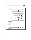
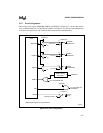
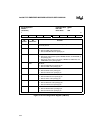
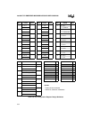
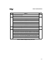
1. Pin Configuration. For each desired pin signal, consult the peripheral configuration
diagram to find the bit value in the pin configuration register that connects the signal to a
device pin. When the signal shares a pin that has no multiplexer, make a note of its
companion signal.
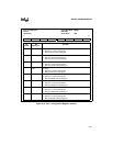
2. Peripheral Configuration. For each peripheral in your design, consult the peripheral
configuration diagram and the peripheral configuration register to find the bit values for
your desired internal connections.
3. Configuration Review. Review the results of steps 1 and 2 to see if the configuration
registers have conflicting bit values. If conflicts exist, follow steps 3a and 3b.
a. Attempt to resolve the pin configuration conflicts first. In some cases you may find that
using a different peripheral channel resolves the conflict.
b. Attempt to resolve peripheral configuration conflicts.
If conflicts remain, consider peripheral substitutions.
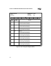
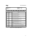
5.5 CONFIGURATION EXAMPLE
This section presents an example of a PC/AT*-compatible configuration. The last set of tables are
blank; you can use them as worksheets as you follow the steps in the configuration process.
5.5.1 Example Design Requirements
The example is a PC/AT-compatible design with the following requirements:
• Interrupt Control Unit:
— External interrupt inputs available at package pins: INT1:0, INT7:4
• Timer Control Unit:
— Counters 0, 1: Clock input is on-chip programmable clock (PSCLK); no signals
connected externally.