


Intel386™ EX EMBEDDED MICROPROCESSOR USER’S MANUAL
12-4
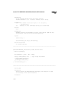
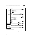
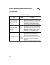
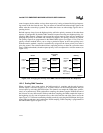
12.1.2 DMA Signals
Table 12-1 describes the DMA signals.
Table 12-1. DMA Signals
Signal
Device Pin
or Internal
Signal
Description
DRQ0
SIO0 RBFDMA0/TXEDMA0
SIO1 TXEDMA1/RBFDMA1
SSIO Transmitter/Receiver
TCU Counter 1
Device pin
(input)
Internal
signals
DMA Channel 0 Requests:
The SIO channel 0 receiver, SIO channel 0 transmitter,
SIO channel 1 receiver, SIO channel 1 transmitter, SSIO
transmitter, SSIO receiver, TCU counter 1 output, or an
external device can request DMA channel 0 service.
These sources are referred to as channel 0 hardware
requests. You can also issue channel 0 software
requests by writing to the DMA software request register.
DRQ1
SIO1 RBFDMA1/TXEDMA1
SIO0 TXEDMA0/RBFDMA0
SSIO Receiver/Transmitter
TCU Counter 2
Device pin
(input)
Internal
signals
DMA Channel 1 Requests:
The SIO channel 1 receiver, SIO channel 1 transmitter,
SIO channel 0 transmitter, SIO channel 0 receiver, SSIO
receiver, SSIO transmitter, TCU counter 2 output, or an
external device can request DMA channel 1 service.
These sources are referred to as channel 1 hardware
requests. You can also issue channel 1 software
requests by writing to the DMA software request register.
DACK
n
# Device pin
(output)
DMA Channel
n
Acknowledge:
Indicates that channel
n
is ready to service the
requesting device. An external device uses the DRQ
n
pin to request DMA service; the DMA uses the DACK
n#
pin to indicate that the request is being serviced.
EOP# Device pin
(input/open-
drain output)
End-of-process:
As an input:
Activating this signal terminates a DMA transfer.
As an output:
This signal is activated when a DMA transfer completes.