12-9
DMA CONTROLLER
12.2.3 Starting DMA Transfers
Internal I/O, external I/O, or memory can request DMA service. The internal I/O requesters (the
asynchronous serial I/O, synchronous serial I/O, and timer control units) are internally connected
to the DMA request inputs. You must connect an external I/O source to the DMA DRQn; when
you are using fly-by mode, you must also connect an external I/O source to the DACKn# signals.
In addition, memory mapped I/O peripherals may use DRQn/DACKn#. DACKn# is active during
the entire fly-by mode transfer, but during a two-cycle mode transfer it is only active during the
access to the requester. These sources make up the DMA hardware request sources. The DMA
unit also contains a software request register that allows you to generate software DMA requests.
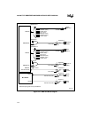
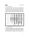
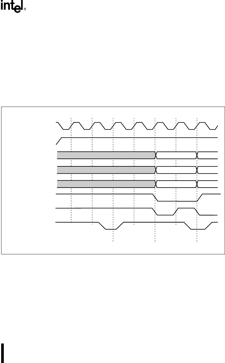
This allows memory-to-memory transfers. Figure 12-4 shows the timing for the start of a DMA
transfer.
Figure 12-4. Start of a Two-cycle DMA Transfer Initiated by DRQ
n
12.2.4 Bus Control Arbitration
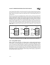
The bus arbiter services bus control requests from the two DMA channels, an external device, and
the refresh control unit. The DMA channels interface with the bus arbiter through its DMA chan-
nel request signals (DREQn) and its DMA channel acknowledge signals (DMAACKn#). Other
external bus masters interface with the bus arbiter through similar request and acknowledge sig-
nals, the HOLD and HOLDA signals respectively. The refresh control unit gains bus control
through an internal Refresh request. The REFRESH# status pin indicates that the Refresh Control
Unit has gained bus control and that a valid refresh cycle is being executed. After receiving a bus
A2480-02
CLKOUT
DRQ
n
A25:1
BHE#, BLE#
M/IO#
DACK
n
#
ADS#
READY#
T
x
Ti T1 T1T
x
Ti T2
x
Cycle
Transition to DMA
Cycle
DMA Cycle


