7-5
SYSTEM MANAGEMENT MODE
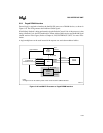
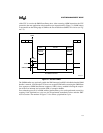
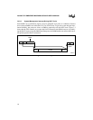
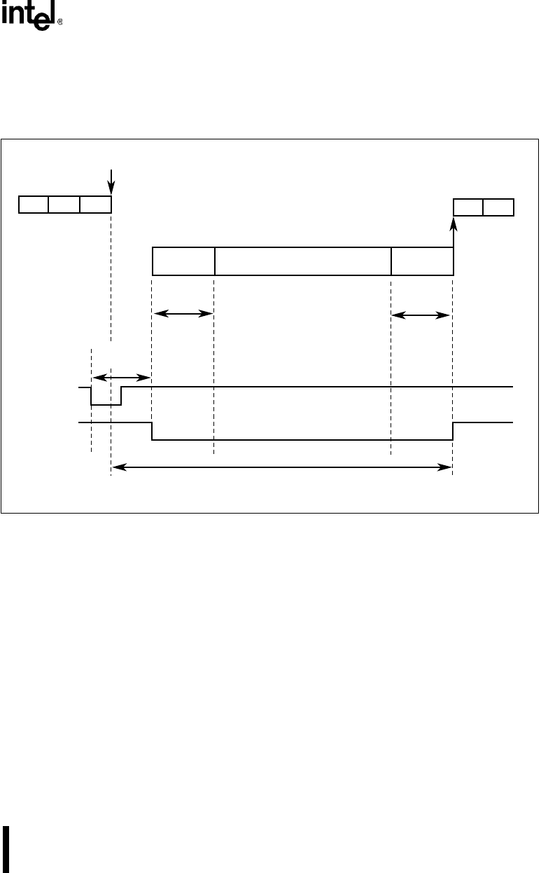
of the CPU is saved to the SMM State Dump Area. After executing a RSM instruction, the CPU
proceeds to the next application code instruction (see instruction #4 in Figure 7-1). SMM latency
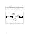
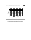
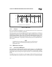
is measured from the falling edge of SMI# to the first ADS# where SMIACT# is active (see Fig-
ure 7-2).
Figure 7-1. Standard SMI#
The SMM handler may optionally enable the NMI interrupt, but NMI is disabled when the SMM
handler is entered. (Note that the CPU does not recognize NMI while executing the SMM State
Save sequence or SMM State Resume sequence.) NMI is always enabled following the comple-
tion of the first interrupt service routine (ISR) or exception handler.
Even when the processor is in SMM, address pipelined bus cycles can be performed correctly by
asserting NA#. Pipelined bus cycles can also be performed immediately before and after SMI-
ACT# assertion. The numbers in Figure 7-2 also reflect a pipelined bus cycle.
A2510-02
State
Save
SMI#
SMM
Handler
Instr
State
Resume
Instr Instr
#1 #2
#4 #5
InstrInstr
#3
SMI#
SMIACT#
SMI
Latency
Interrupts
Blocked
2nd SMI# is blocked
Interrupts
Blocked


