


6-3
BUS INTERFACE UNIT
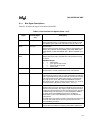
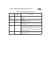
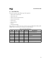
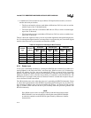
6.1.1 Bus Signal Descriptions
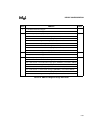
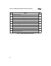
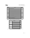
Table 6-1 describes the signals associated with the BIU.
Table 6-1. Bus Interface Unit Signals (Sheet 1 of 2)
Signal
Device Pin or
Internal Signal
only
Description
A25:1 Device pins Address Bus:
Outputs physical memory or I/O addresses. These signals are valid
when ADS# is active and remain valid until the next T1, T2P, or Ti.
ADS# Device pin Address Strobe:
Indicates that the processor is driving a valid bus-cycle definition and
address. (The processor is driving W/R#, D/C#, M/IO#, WR#, RD#,
UCS#, CS6:0#, LOCK#, REFRESH#, A25:1, BHE#, and BLE# on its
pins.)
BHE#
BLE#
Device pins Byte Enable Outputs:
Indicates which byte of the 16-bit data bus of the processor is being
transferred.
BHE# BLE# Output
0 0 word transfer
0 1 upper byte (D15:8) transfer
1 0 lower byte (D7:0) transfer
1 1 refresh cycle
BS8# Device pin Bus Size:
Indicates that the currently addressed device is an 8-bit device.
D15:0 Device pins Data Bus:
Inputs data during memory read, I/O read, and interrupt acknowledge
cycles; outputs data during memory write and I/O write cycles. During
reads, data is latched at the falling edge of phase 2 (coincides with
rising edge of PH1) of T2, T2P, or T2i when READY# is sampled
active. During writes, this bus is driven during phase 2 of T1 and T1P
and remains active until phase 2 of the next T1, T1P, or Ti.
LBA# Device pin Local Bus Access:
Indicates that the processor provides the READY# signal internally to
terminate a bus transaction. This signal is active when the processor
accesses an internal peripheral or when the chip-select unit generates
the READY# signal for accesses to an external peripheral. LBA# is
also active when internal READY# generation is enabled for
Halt/Shutdown cycles and the Watchdog Timer Unit’s Bus Monitor
Mode timeouts.
The LBA# signal goes active in the first T2 state and stays active until
the first T2, T2i or T2P state of the next cycle that does not have
internal READY# generation.
LOCK# Device pin Bus Lock:
Prevents other bus masters from gaining control of the system bus.