Intel386™ EX EMBEDDED MICROPROCESSOR USER’S MANUAL
18-4
18.2.2 Test Access Port (TAP) Controller
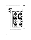
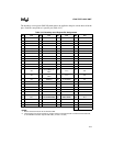
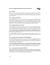
The TAP controller is a finite-state machine that is capable of 16 states (Figure 18-2). Three of its
states provide the basic actions required for testing:
• Applying stimulus (update-data-register)
• Executing a test (run-test/idle)
• Capturing the response (capture-data-register)
Its remaining states support loading instructions, shifting information toward TDO, scanning
pins, and pausing to allow time for the tester to perform other operations.
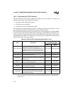
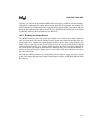
The TAP controller changes state only in response to the assertion of the test-reset input (TRST#)
or the state of the mode-select pin (TMS) on the rising edge of TCK. TRST# causes the TAP con-
troller to enter its test-logic-reset state, and the state of TMS on the rising edge of TCK controls
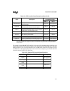
the subsequent states.Table 18-2 describes the states and Figure 18-2 illustrates how the TAP state
machine moves from one state to another.
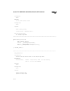
Table 18-2. TAP Controller State Descriptions (Sheet 1 of 2)
State Description
Next State
(on TCK Rising Edge)
TMS = 0 TMS = 1
Test-Logic-Reset
Resets the test-logic unit and forces the IDCODE
instruction into the instruction register. (In
components that have no IDCODE instruction, the
BYPASS instruction is loaded instead.) Test logic is
disabled; the device is in normal operating mode.
Run-Test/Idle Test-Logic-Reset
Run-Test/Idle Executes a test or disables the test logic. Run-Test/Idle Select-DR-Scan
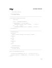
Select-DR-Scan
Selects the data register to be placed in the serial
path between TDI and TDO.
Capture-DR Select-IR-Scan
Capture-DR
Parallel loads data into the active data register, if
necessary. Otherwise, the active register retains its
previous state.
Shift-DR Exit1-DR
Shift-DR
The active register shifts data one stage toward
TDO on each TCK rising edge.
Shift-DR Exit1-DR
Exit1-DR The active register retains its previous state. Pause-DR Update-DR
Pause-DR
The active register temporarily stops shifting data
and retains its previous state.
Pause-DR Exit2-DR
Exit2-DR The active register retains its previous state. Shift-DR Update-DR
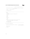
Update-DR
Applies stimulus to the device. Data is latched onto
the active register’s parallel output on the falling
edge of TCK. If the register has no parallel output, it
retains its previous state.
Run-Test/Idle Select-DR-Scan
NOTE: By convention, the abbreviation
DR
stands for
data register
, and
IR
stands for
instruction register
.
The
active register
is the register that the current instruction has placed in the serial path between
TDI and TDO.


