


18-5
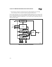
JTAG TEST-LOGIC UNIT
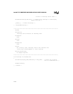
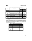
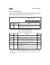
For example, assume that the TAP controller is in its test-logic-reset state and you want it to start
shifting the contents of the instruction register from TDI toward TDO (Shift-IR state). This state
change requires a zero, two ones, then two zeros on TMS at the next five rising edges of TCK
(see Table 18-3). By supplying the proper values in the correct sequence, you can move the TAP
controller from any state to any other state.
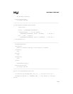
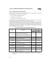
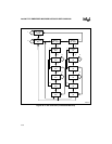
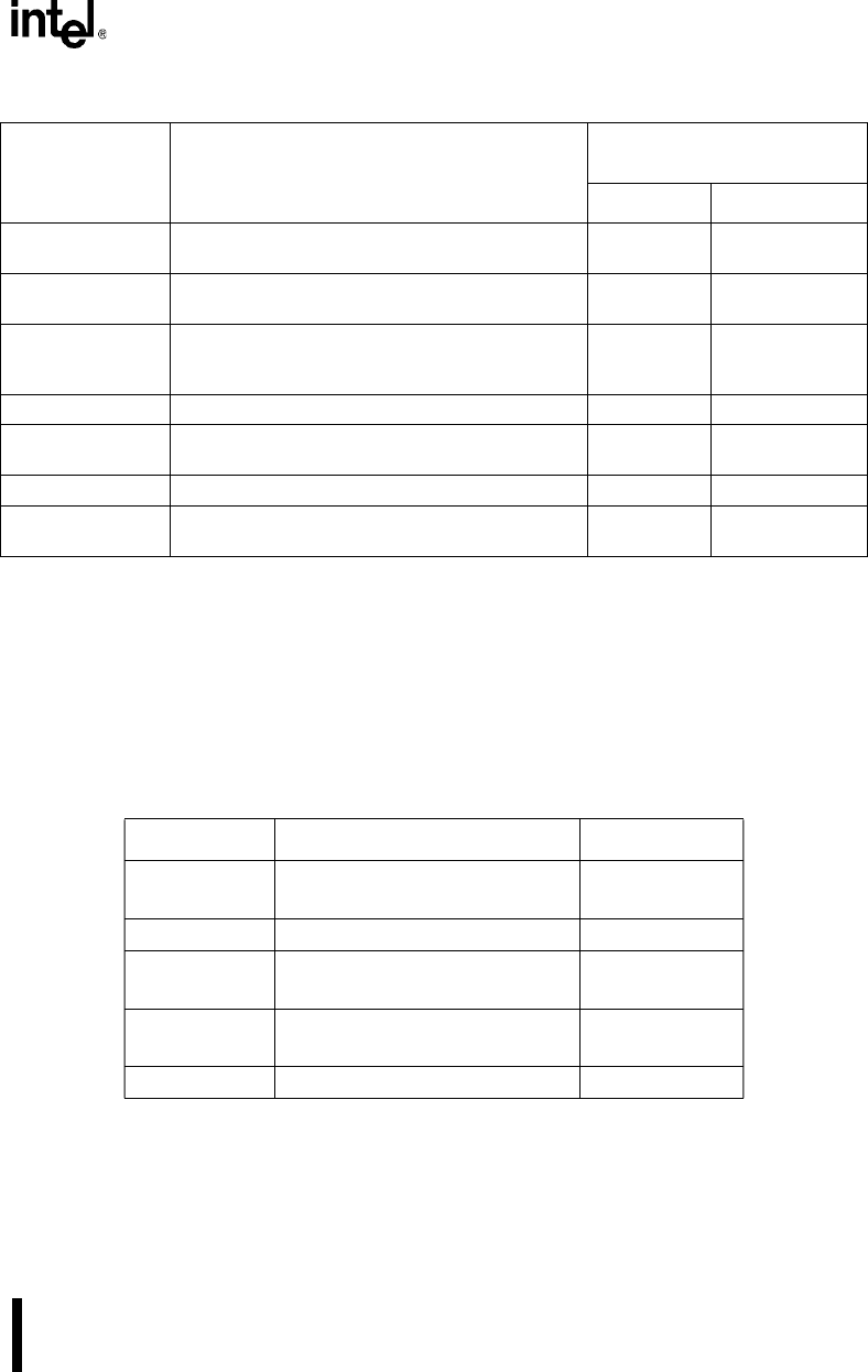
Select-IR-Scan
Test-logic is idle and the instruction register retains
its previous state.
Capture-IR Test-Logic-Reset
Capture-IR
Loads the SAMPLE/PRELOAD instruction
instruction (0001) into the instruction register.
Shift-IR Exit1-IR
Shift-IR
Shifts the SAMPLE/PRELOAD instruction one
stage toward TDO while shifting the new instruction
in from TDI on each rising edge of TCK.
Shift-IR Exit1-IR
Exit1-IR The instruction register retains its previous state. Pause-IR Update-IR
Pause-IR
The instruction register temporarily stops shifting
and retains its previous state.
Pause-IR Exit2-IR
Exit2-IR The instruction register retains its previous state. Shift-IR Update-IR
Update-IR
Latches the current instruction onto the instruction
register’s parallel output on the falling edge of TCK.
Run-Test/Idle Select-DR-Scan
Table 18-3. Example TAP Controller State Selections
Initial State TMS Value at TCK Rising Edge Resulting State
Test-Logic-
Reset
0
Run-Test/Idle
Run-Test/Idle
1
Select-DR-Scan
Select-DR-
Scan
1
Select-IR-Scan
Select-IR-
Scan
0
Capture-IR
Capture-IR
0
Shift-IR
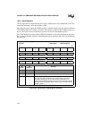
Table 18-2. TAP Controller State Descriptions (Sheet 2 of 2)
State Description
Next State
(on TCK Rising Edge)
TMS = 0 TMS = 1
NOTE: By convention, the abbreviation
DR
stands for
data register
, and
IR
stands for
instruction register
.
The
active register
is the register that the current instruction has placed in the serial path between
TDI and TDO.