Intel386™ EX EMBEDDED MICROPROCESSOR USER’S MANUAL
5-14
5.2.4 Asynchronous Serial I/O Configuration
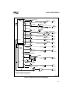
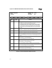
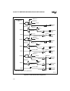
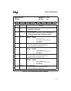
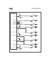
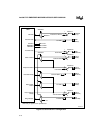
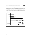
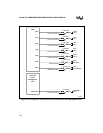
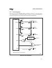
Figures 5-8 and 5-9 show the asynchronous serial I/O unit configuration, consisting of channels
SIO0 and SIO1. Each channel has one output (SIOINT0, SIOINT1) to the interrupt control unit
(see Figure 5-4) and two outputs to the DMA unit. (These signals do not go to package pins.)
SIOINTn is active when any one of the SIO status signals (receiver line status, receiver buffer
full, transmit buffer empty, modem status) is set and enabled. All SIO0 pins are multiplexed with
I/O port signals.
Using SIO1 precludes using DMA channel 1 for external DMA requests due to the multiplexing
of the transmit and receive signals with DMA signals (RXD1/DRQ1, TXD1/DACK1#).
NOTE
Using SIO1 modem signals RTS1#, DSR1#, DTR1#, and RI1# precludes use
of the SSIO unit.


