Intel386™ EX EMBEDDED MICROPROCESSOR USER’S MANUAL
18-2
• Place all device output pins into their inactive drive (high-impedance) state, allowing
external hardware to drive connections that the processor normally drives
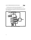
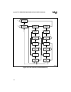
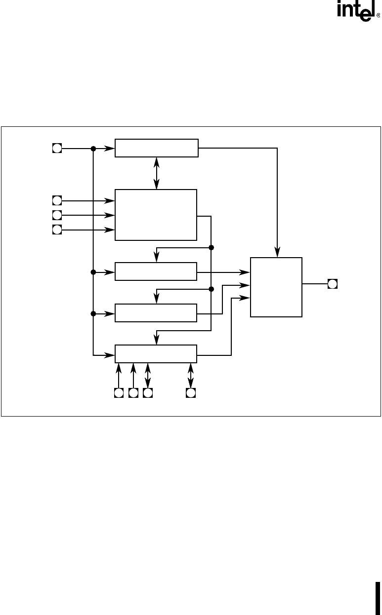
The test-logic unit (Figure 18-1) is fully compliant with IEEE Standard 1149.1. It consists of the
test access port (TAP), the test access port controller, the instruction register (IR), and three data
registers (IDCODE, BYPASS, and BOUND). It also includes logic for generating necessary
clock and control signals.
Figure 18-1. Test Logic Unit Connections
A2340-01
IR Register
TAP
Controller
IDCODE Register
BYPASS Register
BOUND Register
TRST#
TDO
TCK
TDI
Output
Stage
. . . . . .
TMS


