


Intel386™ EX EMBEDDED MICROPROCESSOR USER’S MANUAL
12-8
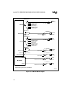
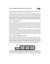
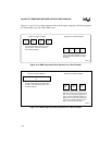
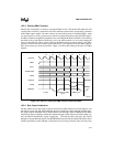
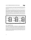
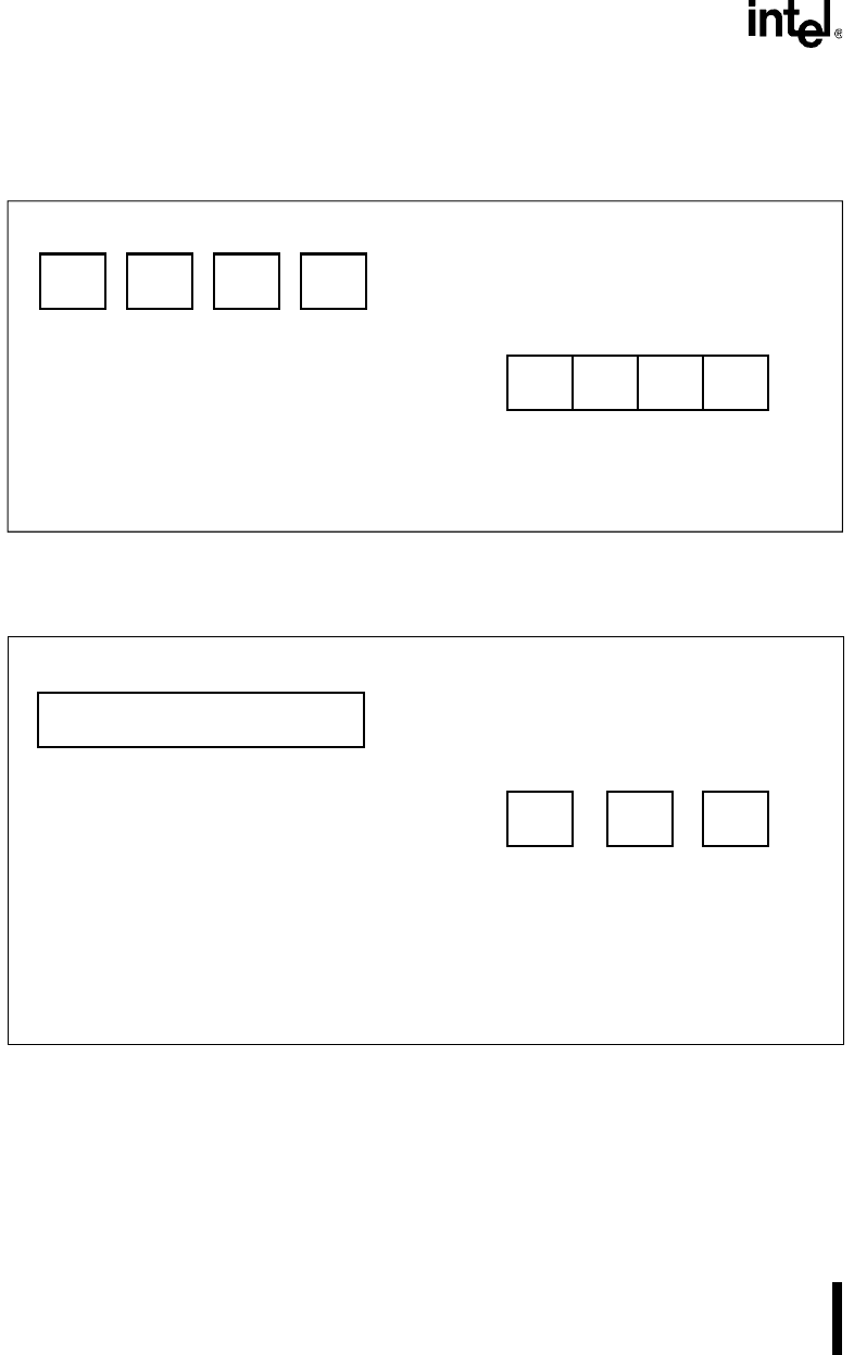
Figures 12-2 and 12-3 are simple diagrams of how the Temporary Register is filled and emptied
for a Read DMA cycle and a Write DMA cycle.
Figure 12-2. DMA Temporary Buffer Operation for a Read Transfer
Figure 12-3. DMA Temporary Buffer Operation for A Write Transfer
A3381-01
Filling the Temporary Register
DREQ
n
#1
DREQ
n
#2
DREQ
n
#3
DREQ
n
#4
Emptying the Temporary Register
Write
#1
Write
#1
Write
#1
Write
#1
Four separate requests each with a read
of the requester. Each byte is stored in
the Temporary Register.
Once the Temporary Resister is full, the
DMA does four burst writes to the target
to empty it.
A3382-01
Filling the Temporary Register
DREQ
n
#1
Emptying the Temporary Register
A single request with four separate reads of
the target. Each read stores a byte in the
Temporary Register.
Once the Temporary Resister is full, the
DMA does a write cycle to transfer the first
byte from the Temporary Register to the
target. On each subsequent request, the
DMA performs a write cycle transferring a
byte from the Temporary Register to the
target. This continues until empty.
DREQ
n
#2
DREQ
n
#3
DREQ
n
#4