


Intel386™ EX EMBEDDED MICROPROCESSOR USER’S MANUAL
9-8
processing of a lower-level slave interrupt. The special fully nested
mode is generally used by the master in a cascaded system.
Special mask In some applications, you may want to allow lower-level requests
interrupt the processing of higher-level interrupts. The special mask
mode supports these applications. Unlike the special-fully nested and
fully nested modes, which are selected during ICU initialization, the
special mask mode can be enabled and disabled during program
operation. When special mask mode is enabled, only interrupts from
the source currently in service are inhibited. All other interrupt
requests (of both higher or lower levels) are passed on.
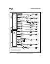
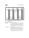
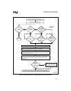
When the internal slave receives an interrupt request, it passes that request to the master. The mas-
ter receives all internal slave interrupt requests on its IR2 signal. This means that in fully nested
mode, higher-level slave requests cannot interrupt lower-level slave interrupts. For example, sup-
pose the slave gets an interrupt request on its IR7 signal. The slave sends the interrupt request to
the master’s IR2 signal (assuming the slave’s IR7 interrupt is enabled and has sufficient priority).
The master sends the interrupt request to the core (assume the master’s IR2 interrupt is enabled
and has sufficient priority). The core initiates an interrupt acknowledge cycle and begins process-
ing the interrupt. Next, the slave gets an interrupt request on its IR0 signal (assume IR0 is as-
signed a higher level than IR7). It then sends another IR2 to the master.
When the master is in fully nested mode, it does not relay the request to the core because the core
is in the process of servicing the previous IR2 interrupt and only a higher-level request can inter-
rupt its process (IR2 is not higher than IR2).
When the master is in special fully nested mode, the request is passed through to the core (IR2 is
equal to IR2).
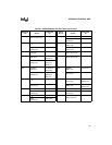
9.2.3 Interrupt Vectors
Each interrupt request has a corresponding interrupt vector number. The interrupt vector number
is a pointer to a location in memory where the address of the interrupt’s service routine is stored.
The relationship between the interrupt vector number and the location in memory of the inter-
rupt’s service routine address depends on the system’s programmed operating mode (real, pro-
tected, or virtual86). Chapter 9 of the Intel386™ SX Microprocessor Programmer’s Reference
Manual explains this relationship.
During an interrupt acknowledge cycle, the ICU puts the interrupt’s vector number on the bus.
From the interrupt vector number and the system’s operating mode, the core determines where to
find the address of the interrupt’s service routine.
You must initialize each 82C59A with an interrupt vector base number. The 82C59As determine
the vector number for each interrupt request from this base number. The base vector number cor-
responds to the IR0 signal’s vector number and must be on an 8-byte boundary.
Other vector numbers are determined by adding the line number of the IR signal to the base. For
example, if the base vector number is 32, the IR5 vector number is 37. Valid vector numbers for
maskable interrupts range from 32 to 255. Because the base vector number must reside on an
8-byte boundary, the valid base vector numbers are 32 + n
×
8 where 0 ≤ n ≤ 27.