


Intel386™ EX EMBEDDED MICROPROCESSOR USER’S MANUAL
5-2
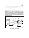
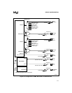
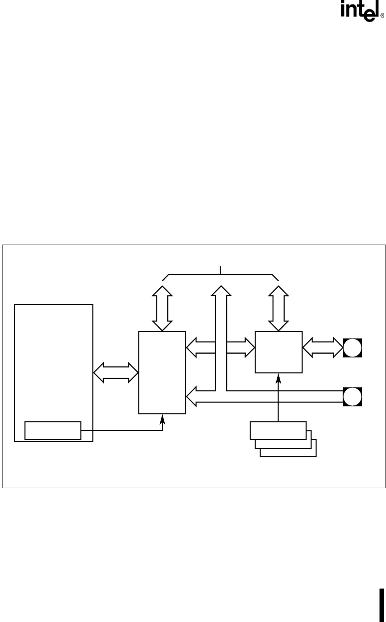
Figure 5-1 shows Peripheral A and its connections to other peripherals and the package pins. The
“Internal Connection Logic” provides three kinds of connections:
• Connections between peripherals
• Connections to package pins via multiplexers
• Direct connections to package pins without multiplexers
The internal connection logic is controlled by the Peripheral A configuration register.
Each pin multiplexer (“Pin Mux”) connects one of two internal signals to a pin. One is a periph-
eral signal. The second signal can be an I/O port signal or a signal from/to another peripheral. The
pin multiplexers are controlled by the pin configuration registers. Some input-only pins without
multiplexers (“Shared Pins w/o Muxes”) are routed to two different peripherals. Your design
should use only one of the inputs and disable or ignore the input going to the second peripheral.
Together, the peripheral configuration registers and the pin configuration registers allow you to
select the peripherals to be used, to interconnect them as your design requires, and to bring se-
lected signals to the package pins.
Figure 5-1. Peripheral and Pin Connections
A2535-01
Microprocessor
Peripheral A
Peripheral A
Configuration
Register
Pin
Muxes
Internal
Connection
Logic
Peripherals B, C, D, ...
Pins
with
Muxes
Shared Pins
w/o Muxes
Pin Configuration Registers
Control
Control