5-29
DEVICE CONFIGURATION
— Counter 2: Clock input is on-chip programmable clock (PSCLK); no signals connected
to package pins
• DMA Unit:
— Not Used
• Asynchronous Serial I/O channel 0 (SIO0):
— Clock input is the internal clock SERCLK
— RXD0, TXD0 connected to package pins
— Modem Signals connected internally.
• Asynchronous Serial I/O channel 1 (SIO1):
— Clock input is the internal clock SERCLK
— Modem signals externally connected
• Synchronous Serial I/O (SSIO):
— Not Used
• Chip Select:
— Chip select signals CS6#, CS5:1#, UCS# connected to package pins
• Core and Bus Arbiter:
— Coprocessor signals connected to package pins
— HOLD and HLDA not connected to package pins
— LOCK# and PWRDOWN not connected to package pins
5.5.2 Example Design Solution
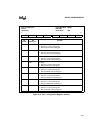
The configuration register bit values for the example design are recorded in the following abbre-
viated register tables. Blank worksheets are provided for you to use when designing your system.
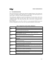
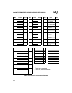
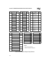
Table 5-4 summarizes the bit selections you would need to make in the pin configuration registers
to implement the example design. Tables 5-5 through 5-8 summarize the bit selections you would
make in the peripheral configuration registers.


