Intel386™ EX EMBEDDED MICROPROCESSOR USER’S MANUAL
11-12
11.2.4 Modem Control
The modem control logic provides interfacing for four input signals and two output signals used
for handshaking and status indication between the SIOn and a modem or data set. An external
modem or data set uses the input signals to inform the SIOn when:
• It is ready to establish a communications link (DSRn#)
• It has detected a data carrier signal (DCDn#)
• It has detected a telephone ringing signal (RIn#)
• It is ready to exchange data (CTSn#)
The SIOn uses its output signals to inform the modem or data set when it is ready to establish a
communication link (DTRn#), and when it is ready to exchange data (RTSn#).
The modem output signals can be internally connected to the modem input signals using the SIO
configuration register. In this case, the modem input signals are disconnected from the pins,
RTSn# is connected to CTSn#, DTRn# is connected to both DSRn# and DCDn#, and V
CC
is con-
nected RIn#.
The SIO contains status flags that indicate the current state of the modem control input signals
and status flags that indicate whether any of the modem control input signals have changed state.
11.2.5 Diagnostic Mode
The SIO channels provide a diagnostic mode to aid in isolating faults in the communications link.
In this mode, data that is transmitted is immediately received. This feature allows the processor
to verify the internal transmit and receive data paths of an SIOn channel.
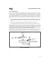
The diagnostic mode connections are as follows:
• The transmitter serial output (TXDn) is set to a logic 1 state.
• The receiver serial input (RXDn) is disconnected from the pin.
• The transmit shift register output is “looped back” into the receive shift register.
• The four modem control inputs (CTSn#, DSRn#, DCDn#, and RIn#) are disconnected from
the pins and controlled by modem control register bits.
• The modem control output pins (RTSn#, DTRn#) are forced to their inactive states.


