11-3
ASYNCHRONOUS SERIAL I/O UNIT
11.1.1 SIO Signals
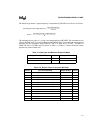
Table 11-1 lists the SIOn signals.
Table 11-1. SIO Signals
Signal
Device Pin or
Internal Signal
Description
Baud-rate
Generator
Clock Source
Internal signal
Device pin
(input)
SERCLK:
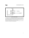
This internal signal is the processor’s input clock, CLK2, divided by
four.
COMCLK:
An external source connected to this pin can clock the SIO
n
baud-rate
generator.
TXD
n
Device pin
(output)
Transmit Data:
The transmitter uses this pin to shift serial data out. Data is
transmitted least-significant bit first.
RXD
n
Device pin
(input)
Receive Data:
The receiver uses this pin to shift serial data in. Data is received least-
significant bit first.
CTS
n
# Device pin
(input)
Clear to Send:
Indicates that the modem or data set is ready to exchange data with
the SIO
n
channel.
DSR
n
# Device pin
(input)
Data Set Ready:
Indicates that the modem or data set is ready to establish the
communications link with the SIO
n
channel.
DCD
n
# Device pin
(input)
Data Carrier Detect:
Indicates that the modem or data set has detected the data carrier.
RI
n
# Device pin
(input)
Ring Indicator:
Indicates that the modem or data set has detected a telephone ringing
signal.
RTS
n
# Device pin
(output)
Request to Send:
Indicates to the modem or data set that the SIO
n
channel is ready to
exchange data.
DTR
n
# Device pin
(output)
Data Terminal Ready:
Indicates to the modem or data set that the SIO
n
channel is ready to
establish a communications link.
SIOINT
n
Internal Signal SIOINT:
This signal is connected to the interrupt control unit and is asserted
(HIGH) when any one of the following interrupt types has an active
condition and is enabled via the IER register: Receiver Error flag,
Received Data Available, Transmitter Holding Register Empty, or
Modem Status. The SIOINT signal is deasserted (LOW) upon the
appropriate interrupt service or reset operation.


