


Intel386™ EX EMBEDDED MICROPROCESSOR USER’S MANUAL
8-8
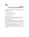
8.3 CONTROLLING POWER MANAGEMENT MODES
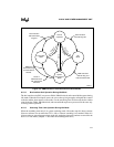
Two power management modes are available: idle and powerdown. These modes are clock dis-
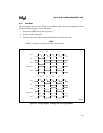
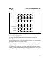
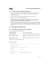
tribution functions controlled by the power control register (PWRCON), shown in Figure 8-5.
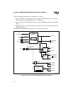
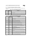
Figure 8-5. Power Control Register (PWRCON)
Power Control Register
PWRCON
(read/write)
Expanded Addr:
ISA Addr:
Reset State:
F800H
—
00H
7 0
— — — — WDTRDY HSREADY PC1 PC0
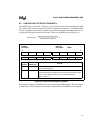
Bit
Number
Bit
Mnemonic
Function
7–4 — Reserved. These bits are undefined; for compatibility with future devices,
do not modify these bits.
3 WDTRDY Watch Dog Timer Ready:
0 = An external READY must be generated to terminate the cycle when
the WDT times out in Bus Monitor Mode.
1 = Internal logic generates READY# to terminate the cycle when the
WDT times out in Bus Monitor Mode.
2 HSREADY Halt/Shutdown Ready:
0 = An external ready must be generated to terminate a HALT/Shutdown
cycle.
1 = Internal logic generates READY# to terminate a HALT/Shutdown
cycle.
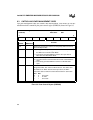
1–0 PC1:0 Power Control:
Program these bits, then execute a HALT instruction. The device enters
the programmed mode when READY# (internal or external) terminates
the halt bus cycle. When these bits have equal values, the HALT
instruction causes a normal halt and the device remains in active mode.
PC1 PC0
0 0 active mode
1 0 idle mode
01powerdown mode
1 1 active mode