


12-13
DMA CONTROLLER
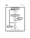
The DMAINT signal is active immediately after the Chaining Process has been entered, as the
channel then perceives the Base Registers to be empty and in need of reloading. It is important to
have the interrupt service routine in place at the time the Chaining Process is entered. The inter-
rupt request is removed when the most significant byte of the Base Target Address is loaded.
NOTE
Since the most significant byte of the Base Target Address only exists in
0FXXXH I/O address space, the Chaining Buffer Transfer Mode cannot be
used in a DOS Compatible-only mode.
The interrupt occurs again when the first buffer transfer expires and the Current Registers are
loaded from the Base Registers. The cycle continues until the Chaining Process is disabled, or the
host fails to respond to DMAINT before the Current Buffer expires.
Exiting the Chaining Process can be done by resetting the Chaining Mode Register. If an interrupt
is pending for the channel when the Chaining Register is reset, the interrupt request is removed.
The Chaining Process can be temporarily disabled by setting the channel’s mask bit in the Mask
Register.
The interrupt service routine for DMAINT has the responsibility of reloading the Base Register
as necessary. It should check the status of the channel to determine the cause of the channel ex-
piration, etc. It should also have access to operating system information regarding the channel, if
any exists. The DMAINT service routine should be capable of determining whether the chain
should be continued or terminated and act on that information.
NOTE
The chaining buffer-transfer mode is not useful with block transfer mode since
the CPU must be able to get control of the bus before the end of the “block” in
order to reprogram the new values into the DMA registers. Since block
transfer mode locks out any other bus requests (except refresh) the processor
cannot regain control of the bus until the entire block has been transferred.
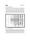
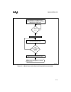
12.2.7 Data-transfer Modes
There are three data-transfer modes (single, block, and demand) that determine how the bytes or
words that make up a buffer of data are transferred. The DMAMOD1 register is used to select a
channel’s data transfer mode.
Single Mode A channel request causes one byte or word (depending on the
selected bus widths) to be transferred. Single mode requires a
channel request for every data transfer within a buffer transfer.
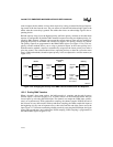
Block Mode A channel request causes the entire buffer of data to be transferred.
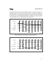
Demand Mode The amount of buffer data (bytes or words) that the channel transfers
depends on how long the channel request input is held active. In this
mode, the channel continues to transfer data while the channel
request input is held active; when the signal goes inactive, the buffer