


11-29
ASYNCHRONOUS SERIAL I/O UNIT
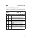
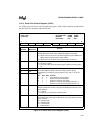
11.3.10 Modem Control Register (MCR
n
)
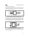
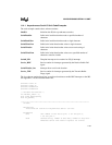
Use MCRn to put the SIOn into a diagnostic test mode. In this mode, the modem input signals
are disconnected from the package pins and controlled by the lower four MCRn bits and the mo-
dem output signals are forced to their inactive states (Figure 11-19). Additionally, the MCRn sig-
nals are also forced into the MSR register bits.
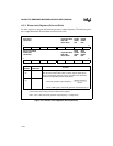
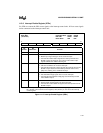
Figure 11-19. Modem Control Signals – Diagnostic Mode Connections
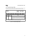
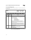
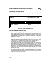
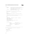
Besides the diagnostic mode, there are two other options for connecting the modem input signals.
You can connect the signals internally using the SIO configuration (SIOCFG) register. The inter-
nal connection mode disconnects the modem input signals from the package pins and connects
the modem output signals to the modem input signals (in this case, the modem output signals re-
main connected to package pins). See Figure 11-20. In this mode, the values you write to MCRn
bits 0 and 1 control the state of the modem’s internal input signals and output pins.
Figure 11-20. Modem Control Signals – Internal Connections
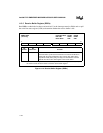
The other option is standard mode. In standard mode, the modem input and output signals are
connected to the package pins. In this mode, the values you write to MCRn bits 0 and 1 control
the state of the modem’s output pins.
A2529-01
CTS#
DSR#
DCD#
RI#
RTS#
DTR#
RTS
n
#
(forced high)
DTR
n
#
(forced high)
MCR
n
.1
MCR
n
.3
MCR
n
.0
MCR
n
.2
Note: MCR
n
.1 indicates that modem control register bit 1 controls the CTS input, and so on.
A2528-01
CTS#
DSR#
DCD#
RI#
RTS#
DTR#
Vcc
RTS
n
#
DTR
n
#