10-19
TIMER/COUNTER UNIT
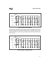
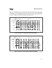
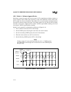
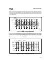
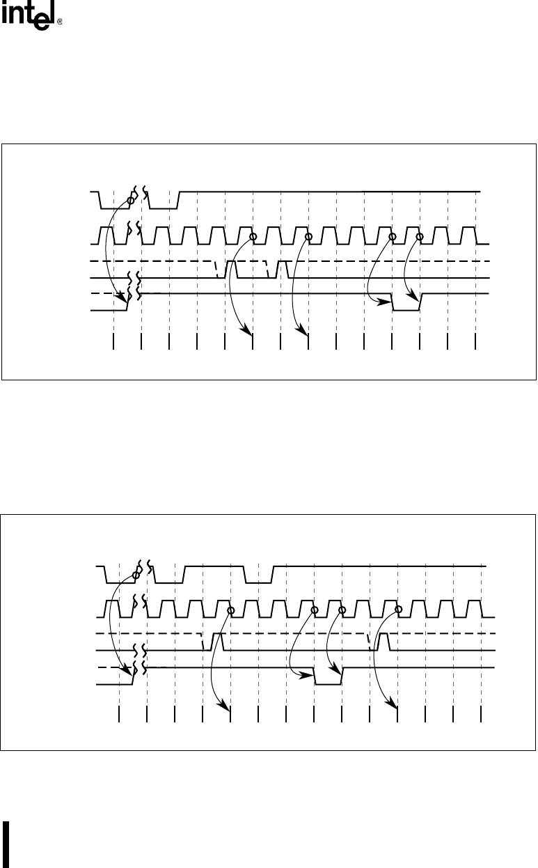
Figure 10-20 shows retriggering the strobe with a gate-trigger. On the CLKINn pulse following
the retrigger, the counter reloads the count. The control logic then decrements the count on each
succeeding CLKINn pulse. OUTn remains high until the count reaches zero, then strobes low for
one CLKINn pulse.
Figure 10-20. Mode 5 – Retriggering the Strobe
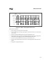
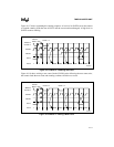
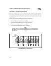
Figure 10-21 shows the writing of a new count value. The counter waits for a gate-trigger to load
the new count; it does not affect the current sequence until the counter receives a trigger. On the
CLKINn pulse following the trigger, the control logic loads the new count. The control logic then
decrements the count on each succeeding CLKINn pulse. OUTn remains high until the count
reaches zero, then strobes low for one CLKINn pulse.
Figure 10-21. Mode 5 – Writing a New Count Value
A2404-01
? ? ? ? ? ? 0003 0002 0003 0002 0001 0000
Writes to
Counter
n
CLKIN
n
GATE
n
OUT
n
Control
Word = 1AH
Count
FFFF
Count = 3
FFFE
? ? ? ? ? 0003 0002 0001 0000 FFFF FFFE 0005
Writes to
Counter
n
CLKIN
n
GATE
n
OUT
n
Control
Word = 1AH
Count
0004
Count = 3
Count = 5
0003
A2405-01
V
CC


