Intel386™ EX EMBEDDED MICROPROCESSOR USER’S MANUAL
9-16
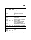
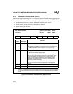
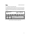
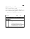
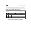
Table 9-2. ICU Registers (Sheet 1 of 2)
Register
Expanded
Address
PC/AT*
Address
Function
P3CFG
(read/write)
0F824H — Port 3 Configuration:
The INT3:0 signals are multiplexed with P3.5:2. This register
determines which signals are connected to the package pins.
When a P3.
n
signal rather than an INT
n
signal is connected to
a package pin, V
SS
is connected to the master’s IR
n
signal.
INTCFG
(read/write)
0F832H — Interrupt Configuration:
Determines the master’s and the slave’s IR signal
connections: SIOINT1 or INT8; SIOINT0 or INT9; V
SS
or INT7;
V
SS
or INT6; SSIOINT or INT5; V
SS
or INT4. Swaps DMAINT
and INT6. Also enables the master’s cascade bus (CAS2:0).
When enabled, the cascade signals appear on the A18:16
address lines during an interrupt acknowledge cycle.
ICW1 (master)
ICW1 (slave)
(write only)
0F020H
0F0A0H
0020H
00A0H
Initialization Command Word 1:
Determines whether interrupt request signals are level
sensitive or edge triggered.
ICW2 (master)
ICW2 (slave)
(write only)
0F021H
0F0A1H
0021H
00A1H
Initialization Command Word 2:
Contains the base interrupt vector number for the 82C59A.
The base interrupt vector is the IR0 vector number, the base
plus one is the IR1 vector number, and so on.
ICW3 (master)
(write only)
0F021H 0021H Initialization Command Word 3:
Identifies the master’s IR signals that are connected to slave
82C59A devices. The internal slave is connected to the
master’s IR2 signal. You can connect external slaves to the
master’s IR1, IR3, IR4, IR5, IR6, and IR7 signals.
ICW3 (slave)
(write only)
0F0A1H 00A1H Initialization Command Word 3:
Indicates that the internal slave is cascaded from the master’s
IR2 signal.
ICW4 (master)
ICW4 (slave)
(write only)
0F021H
0F0A1H
0021H
00A1H
Initialization Command Word 4:
Selects either special-fully nested or fully nested mode and
enables the automatic end-of-interrupt mode.
OCW1 (master)
OCW1 (slave)
(read/write)
0F021H
0F0A1H
0021H
00A1H
Operation Command Word 1:
Masks (disables) individual interrupt request signals.
OCW2 (master)
OCW2 (slave)
(write only)
0F020H
0F0A0H
0020H
00A0H
Operation Command Word 2:
Changes interrupt levels and sends end-of-interrupt
commands.
OCW3 (master)
OCW3 (slave)
(write only)
0F020H
0F0A0H
0020H
00A0H
Operation Command Word 3:
Enables special mask mode, issues the poll command, and
allows access to the interrupt request and in-service registers.
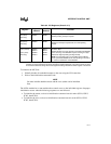
NOTE: All master 82C59A registers are accessed through two expanded or PC/AT addresses; all the slave
registers are accessed through two other expanded or PC/AT addresses. The order in which you write
or read these addresses along with certain register bit settings determines which register is accessed.


