Intel386™ EX EMBEDDED MICROPROCESSOR USER’S MANUAL
9-30
Level triggered The 82C59A recognizes a high level on an IR line as an interrupt
request. A device must maintain the high level until after the falling edge
of the first INTA# pulse. Unlike an edge-triggered IR signal, a level-
triggered IR signal continues to generate interrupts as long as it is
asserted. To avoid continuous interrupts from the same source, a device
must deassert a level-sensitive IR signal before the interrupt handler
issues an end-of-interrupt (EOI) command.
All internal peripherals interface with their respective 82C59As in edge-triggered mode. This is
compatible with the PC/AT bus specification. Each source signal initiates an interrupt by making
a low-to-high transition.
9.4.3 Spurious Interrupts
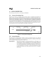
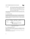
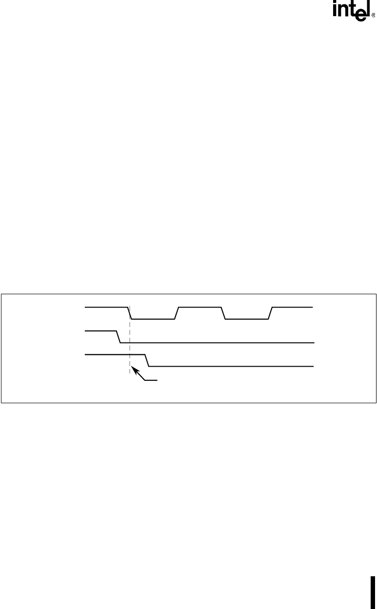
For both edge and level-triggered interrupts, a high level must be maintained on the IR line until
after the falling edge of the first INTA# pulse (see Figure 9-18). A spurious interrupt request is
generated if this stipulation is not met. A spurious interrupt on any IR line generates the same vec-
tor number as an IR7 request. The spurious interrupt, however, does not set the in-service bit for
IR7. Therefore, an IR7 interrupt service routine must check the in-service register to determine
whether the interrupt source was a valid IR7 (the in-service bit is set) or a spurious interrupt (the
in-service bit is cleared).
Figure 9-18. Spurious Interrupts
9.4.4 Cascading Interrupt Controllers
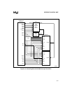
Figure 9-19 is a block diagram showing the connections for two cascaded 82C59As. The PLD
generates READY# (for the second Interrupt Acknowledge Cycle) and INTA# to the external
82C59A devices. The PLD also generates appropriate timings for the INTA# signals to satisfy
82C59A specifications.
The RD# and WR# strobes are used to read and write to the 82C59A registers. These strobes are
inactive during Interrupt Acknowledge Cycles.
A2431-01
INTA#
IR (Valid)
IR sampled on this edge.
IR (Spurious)


