12-5
DMA CONTROLLER
12.2 DMA OPERATION
The following sections describe the operation of the DMA. See “Register Definitions” on page
12-28 for details on implementing DMA Controller options.
12.2.1 DMA Transfers
The DMA transfers data between a requester and a target. The data can be transferred from the
requester to target or vice versa. The target addresses and requester addresses can be located in
either memory or I/O space, and data transfers can be on a byte or word basis. The requester can
be in external device I/O space, in internal peripheral I/O space, or memory mapped I/O. (Very
simply, the requester is the thing that activated DREQn.) An external device or an internal periph-
eral requests service by activating a channel’s request input (DREQn). A requester in memory re-
quests service through the DMA software request register. The requester either deposits data to
or fetches data from the target.
A channel is programmed by writing to a set of requester address, target address, byte count, and
control registers. The address registers specify base addresses for the target and requester, and the
byte count registers specify the number of bytes that need to be transferred to or from the target.
Typically, a channel is programmed to transfer a block of data. Therefore, it is necessary to dis-
tinguish between the process of transferring one byte or word (data transfer) and the process of
transferring the entire block of data (buffer transfer).
The byte count determines the number of data transfers that make up a buffer transfer. After each
data transfer within a buffer transfer, the byte count is decremented (by 1 for byte transfers and
by 2 for word transfers) and the requester and target addresses are either incremented, decrement-
ed, or left unchanged. When the byte count expires (reaches FFFFFFH), the buffer transfer is
complete. If the channel’s end-of-process (EOP#) signal is activated before the byte count ex-
pires, the buffer transfer is terminated.
NOTE
Since the buffer transfer is complete when the byte count reaches FFFFFFH,
the number of bytes transferred is the byte count + 1.
12.2.2 Bus Cycle Options for Data Transfers
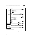
There are two bus cycle options for transferring data, fly-by and two-cycle. Fly-by allows data to
be transferred in one bus cycle. It requires that the requester be in external I/O and the target be
in memory. The two-cycle option allows data to be transferred between any combination of mem-
ory and I/O through the use of a four-byte temporary buffer.
12.2.2.1 Fly-By Mode
The fly-by option performs either a memory write or a memory read bus cycle. A write cycle
transfers data from the requester to the target (memory), and a read cycle transfers data from the
target (memory) to the requester. When a data transfer is initiated, the DMA places the memory
address of the target on the bus and selects the requester by asserting the DACKn# signal. The
requester then either deposits the transfer data on the data bus or fetches the transfer data off the


