


12-27
DMA CONTROLLER
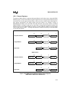
The four interrupt source signals (two per channel) are internally connected (ORed) to the inter-
rupt request output (DMAINT). When an interrupt from DMAINT is detected, you can determine
which signal caused the request by reading the DMA interrupt status register.
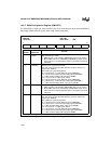
12.2.10 8237A Compatibility
Although the DMA is an enhancement over the 8237A, you can configure it to operate in an
8237A-compatible mode. A list of the features common to the DMA and 8237A and a list of
DMA enhancements follow.
Features common to the DMA and 8237A:
• Data-transfer modes (single, block, and demand)
• Buffer-transfer modes (single and autoinitialize)
• Fly-by data transfer bus cycle option
• Programmed via 8-bit registers
• Transfers between memory and I/O (target must be in memory and requester must be
external)
DMA enhancements:
• Chaining buffer-transfer mode
• Two-cycle data transfer bus cycle option (provides byte assembly and allows memory-to-
memory transfers using only one channel)
• Transfers between any combination of memory and I/O
• Address registers for both the target and the requester; addresses can be incremented,
decremented, or left unchanged during a buffer transfer
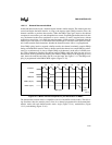
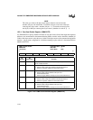
A channel is configured for 8237A compatibility by enabling only the common features and lim-
iting the byte count and the target address modification capability. The 8237A uses a 16-bit target
address and a 16-bit byte count, while the DMA uses a 26-bit target address and a 24-bit byte
count. Therefore, for compatibility, the DMA contains an overflow register that allows you to
configure the target and byte count so that only the lower 16 bits are modified during buffer trans-
fers. With this configuration, the upper byte count bits are ignored; the byte count expires when
it is decremented from 0000H to FFFFH (16-bit versus 24-bit rollovers).