


10-1
CHAPTER 10
TIMER/COUNTER UNIT
The Timer/counter Unit (TCU) has the same basic functionality as the industry-standard 82C54
counter/timer. It contains three independent 16-bit down counters, which can be driven by a pres-
caled value of the processor clock or an external clock. The counters contain two count formats
(binary and BCD) and six different operating modes, two of which are periodic. Both hardware
and software triggered modes exist, providing for internal or external control. The counter’s out-
put signals can appear at device pins, generate interrupt requests, and initiate DMA
transactions.
This chapter is organized as follows:
• Overview (see below)
• TCU Operation (page 10-5)
• Register Definitions (page 10-20)
• Programming Considerations (page 10-33)
10.1 OVERVIEW
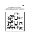
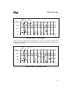
The TCU contains control logic and three independent 16-bit down counters (Figure 10-1). Each
counter has two input signals and one output signal:
CLKINn You can independently connect each counter’s clock input (CLKINn) signal to
either the internal prescaled clock (PSCLK) signal or the external timer clock
(TMRCLKn) pin. This allows you to use either a prescaled value of the
processor’s internal clock or an external clock to drive each counter.
NOTE
The maximum CLKINn frequency, whether connected internally or externally,
is 8 MHz.
GATEn Each counter has a gate (GATEn) input signal. This signal provides counter
operation control. In some of the counter operating modes, a high level on a
counter’s GATEn signal enables or resumes counting and a low level disables or
suspends counting. In other modes, a rising edge on GATEn loads a new count
value. You can independently connect each counter’s GATEn signal to either V
CC
or the external timer gate (TMRGATEn) pin, or you can drive each counter’s
GATEn signal high or low through register bits.
OUTn Each counter contains an output signal called OUTn. You can independently
connect these signals to the external timer clock output (TMROUTn) pins.
OUT0, OUT1, and OUT2 are routed to the interrupt control unit. OUT1 is also
routed to DMA channel 0, and OUT2 is also routed to DMA channel 1.