Intel386™ EX EMBEDDED MICROPROCESSOR USER’S MANUAL
9-22
9.3.5 Initialization Command Word 3 (ICW3)
The ICW3 register contains information about the master/slave connections. For this reason, the
functions of the master’s ICW3 and the slave’s ICW3 differ.
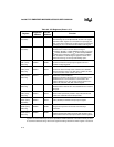
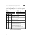
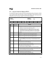
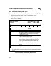
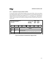
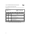
ICW3 (at 0F021H or 0021H) is the master’s cascade configuration register (Figure 9-11). The
master has an internal slave cascaded from its IR2 signal. You can cascade additional slaves from
the master’s IR7, IR6, IR5, IR4, IR3 and IR1 signals. Setting a bit indicates that a slave 82C59A
is cascaded from the corresponding master’s IR signal.
NOTE
Since the internal slave is cascaded from the master’s IR2 signal, you must set
the S2 bit.
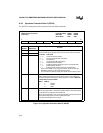
Figure 9-10. Initialization Command Word 3 Register (ICW3 – Master)
Initialization Command Word 3
ICW3 (master)
(write only)
Expanded Addr:
ISA Addr:
Reset State:
F021H
0021H
XXH
7 0
S7 S6 S5 S4 S3 S2 S1 0
Bit
Number
Bit
Mnemonic
Function
7–3 S7:3 Slave IRs
0 = No slave 8259A is attached to the corresponding IR signal of the
master.
1 = A slave 82C59A is attached to the corresponding IR signal of the
master.
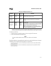
2 S2 0 = Internal slave not used
1 = Internal slave is cascaded from the master’s IR2 signal.
1 S1 Slave IRs
0 = No slave 8259A is attached to the master through the IR1 signal of
the master.
1 = A slave 82C59A is attached to the IR1 signal of the master.
0 — Clear this bit to guarantee device operation.


