


Intel386™ EX EMBEDDED MICROPROCESSOR USER’S MANUAL
12-28
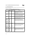
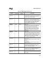
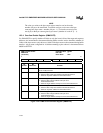
12.3 REGISTER DEFINITIONS
Table 12-3 lists the registers associated with the DMA unit, and the following sections contain bit
descriptions for each register.
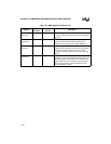
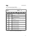
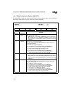
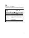
Table 12-3. DMA Registers (Sheet 1 of 3)
Register
Expanded
Address
PC/AT*
Address
Description
PINCFG
(read/write)
F826H — Pin Configuration:
Connects the DMA channel acknowledge
(DMAACK0#, DMAACK1#) and end-of-process
signals to package pins DACK0#, DACK1# and
EOP#, respectively.
DMACFG
(read/write)
F830H — DMA Configuration:
Determines which signal is connected to the DMA
channel request inputs (DREQ
n
). Masks the channel
acknowledge signals (DMAACK0#, DMAACK1#),
which is useful when using internal requesters.
DMACMD1
(write only)
F008H 0008H DMA Command 1:
Simultaneously enables or disables both DMA
channels. Enables the rotating method for changing
the bus control priority structure.
DMA0REQ0
DMA0REQ1
DMA0REQ2
DMA0REQ3
DMA1REQ0
DMA1REQ1
DMA1REQ2
DMA1REQ3
(read/write)
F010H
F010H
F011H
F011H
F012H
F012H
F013H
F013H
—
—
—
—
—
—
—
—
Channel 0 and 1 Requester Address:
Contains channel
n
’s 26-bit requester address.
During a buffer transfer, this address may be
incremented, decremented, or left unchanged.
Reading these registers returns the current address.
DMA0TAR0
DMA0TAR1
DMA0TAR2
DMA0TAR3
DMA1TAR0
DMA1TAR1
DMA1TAR2
DMA1TAR3
(read/write)
F000H
F000H
F087H
F086H
F002H
F002H
F083H
F085H
0000H
0000H
0087H
—
0002H
0002H
0083H
—
Channel 0 and 1 Target Address:
Contains channel
n
’s 26-bit target address. During a
buffer transfer, this address may be incremented,
decremented, or left unchanged. Reading these
registers returns the current address.
DMA0BYC0
DMA0BYC1
DMA0BYC2
DMA1BYC0
DMA1BYC1
DMA1BYC2
(read/write)
F001H
F001H
F098H
F003H
F003H
F099H
0001H
0001H
—
0003H
0003H
—
Channel 0 and 1 Byte Count:
Contains channel
n
’s 24-bit byte count. During a
buffer transfer, this byte count is decremented.
Reading these registers returns the current byte
count.