


5-7
DEVICE CONFIGURATION
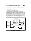
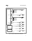
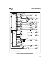
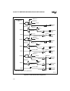
5.2.2 Interrupt Control Unit Configuration
The interrupt control unit (ICU) comprises two 82C59A interrupt controllers connected in cas-
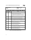
cade, as shown in Figure 5-4. (See Chapter 9 for more information.) Figure 5-5 describes the in-
terrupt configuration register (INTCFG).
The ICU receives requests from eight internal sources:
• Three outputs from the timer/counter unit (OUT2:0)
• An output from each of the serial I/O units (SIOINT1:0)
• An output from the synchronous serial I/O unit (SSIOINT)
• An output from the DMA unit (DMAINT)
• An output from the WDT unit (WDTOUT#)
In addition, the ICU controls the interrupt sources on ten external pins:
• INT3:0 (multiplexed with I/O port signals P3.5:2) are enabled or disabled by the P3CFG
register (see Figure 5-18).
• INT7:4 share their package pins with four TCU inputs: TMRGATE1, TMRCLK1,
TMRGATE0, and TMRCLK0. These signal pairs are not multiplexed; however, the pin
inputs are enabled or disabled by the INTCFG register.
• INT9:8 share their pins with TMROUT1, TMROUT0, P3.1, P3.0
The three cascade outputs (CAS2:0) should be enabled when an external 82C59A module is con-
nected to one of the INT9:8 or INT3:0 signals. The cascade outputs are ORed with address lines
A18:16. See “Interrupt Acknowledge Cycle” on page 6-23 for details.
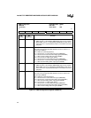
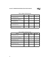
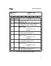
Use Tables 5-1 and 5-2 to configure the functionality of the master 82C59A’s IR3, IR4 inputs, and
the associated external pins.