9-23
INTERRUPT CONTROL UNIT
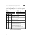
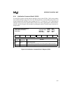
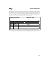
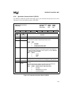
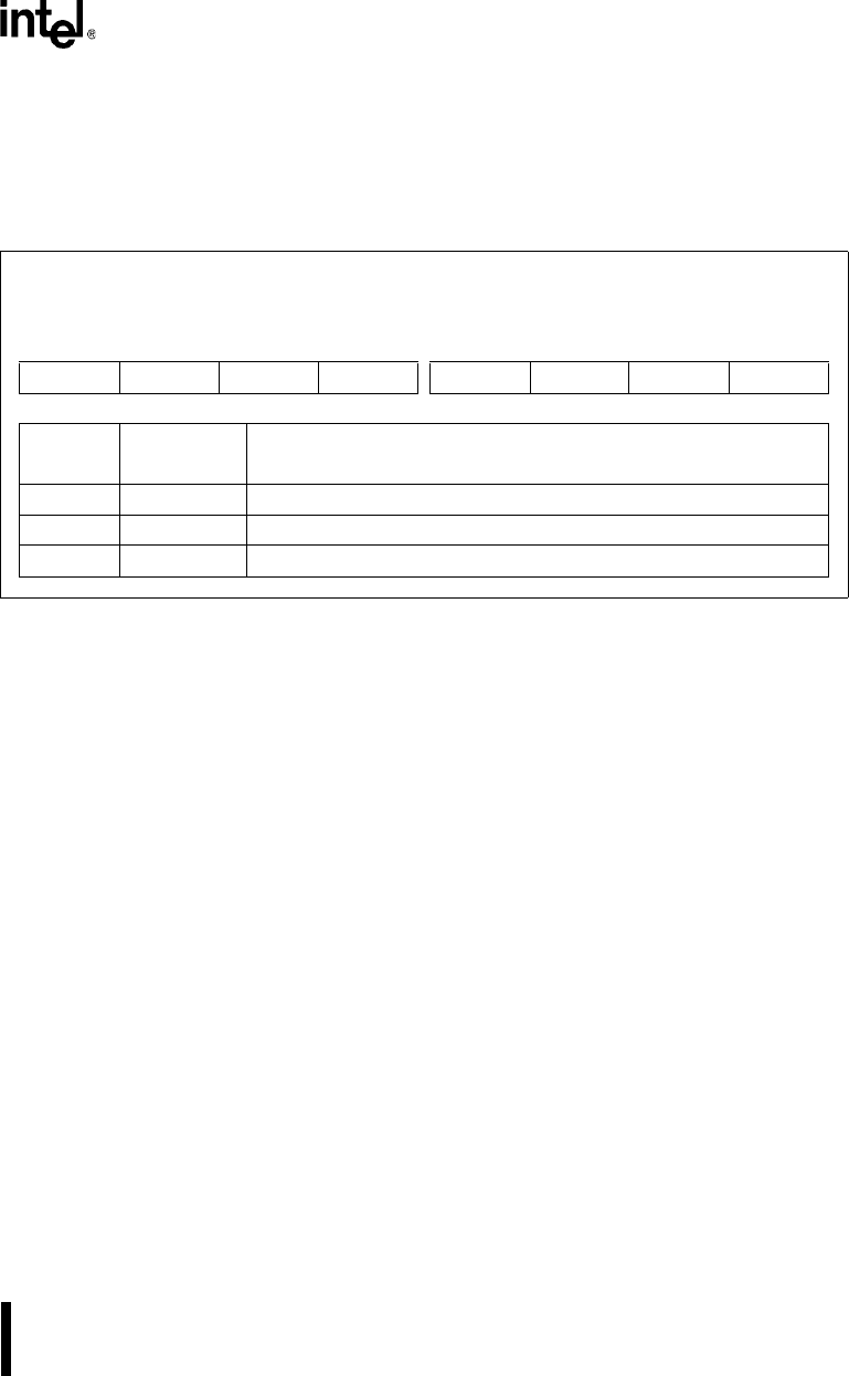
ICW3 (at 0F0A1H or 00A1H) is the internal slave ID register (Figure 9-11). Use this register to
indicate that the slave is cascaded from the master’s IR2 signal. This gives the internal slave an
ID of 2. Each slave device uses the IDs to determine whether it is the slave being addressed. Dur-
ing a slave access, the slave’s ID is driven on the master’s CAS2:0 signals. If these signals are
enabled (bit 7 of INTCFG is 1), they appear on the A18:16 address lines.
Figure 9-11. Initialization Command Word 3 Register (ICW3 – Slave)
Initialization Command Word 3
ICW3 (slave)
(write only)
Expanded Addr:
ISA Addr:
Reset State:
F0A1H
00A1H
XXH
7 0
0000 0010
Bit
Number
Bit
Mnemonic
Function
7–2 — Clear these bits to guarantee device operation.
1 — Set this bit to guarantee device operation.
0 — Clear this bit to guarantee device operation.


