10-3
TIMER/COUNTER UNIT
10.1.1 TCU Signals and Registers
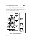
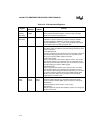
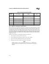
Table 10-1 and Table 10-2 lists the signals and registers associated with the TCU.
Table 10-1. TCU Signals
Signal
Device Pin or
Internal Signal
Description
PSCLK Internal signal Prescaled Clock:
This is one of the two possible connections for the counter’s CLKIN
n
signal. PSCLK is an internal signal that is a prescaled value of the
processor internal clock. The clock and power management unit
contains a programmable divider that determines the PSCLK frequency.
See “Controlling the PSCLK Frequency” on page 8-7, for information on
how to program PSCLK’s frequency.
TMRCLK0
TMRCLK1
TMRCLK2
Device pin Timer Clock Input:
This is one of the two possible connections for the counter’s CLKIN
n
signal. You can drive a counter with an external clock source by
connecting the clock source to the counter’s TMRCLK
n
pin.
TMRGATE0
TMRGATE1
TMRGATE2
Device pin Timer Gate Input:
This input can be connected to the counter’s GATE
n
input to control the
counter’s operation. In some of the counter’s operating modes, a high
level on GATE
n
enables or resumes counting, while a low level disables
or suspends counting. In other modes, a rising edge on GATE
n
loads a
new count value.
TMROUT0
TMROUT1
TMROUT2
Device pin Timer Output:
The counter’s OUT
n
signal can be connected to this pin. The operation,
and consequently the waveform, of the output depends on the counter’s
operating mode.


