13-23
SYNCHRONOUS SERIAL I/O UNIT
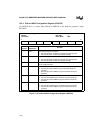
13.3.7 SSIO Control 2 Register (SSIOCON2)
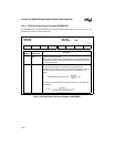
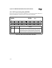
Use the control bits TXMM and RXMM in SSIOCON2 to put the transmitter or receiver in mas-
ter or slave mode. The AUTOTXM bit is used to determine if the TEN bit controls the transmit-
ting of the data.
Figure 13-21. SSIO Control 2 Register (SSIOCON2)
SSIO Control 2
SSIOCON2
(read/write)
Expanded Addr:
ISA Addr:
Reset State:
F488H
—
00H
7 0
———— —AUTOTXMTXMMRXMM
Bit
Number
Bit
Mnemonic
Function
7–3 — Reserved. These bits are undefined; for compatibility with future devices,
do not modify these bits.
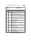
2 AUTOTXM Automatic Transmit off mode for master mode
0 = Clearing this bit puts the TEN bit into normal operation
1 = Setting this bit and the TXMM bit causes TEN to be ignored. Every
time a word is loaded into the transmit shift register from the transmit
holding buffer it is transmitted out and then stops.
1 TXMM Transmit Master Mode:
0 = Clearing this bit puts the transmitter in slave mode. In slave mode, an
external device controls the transmit serial communications. An input
on the STXCLK pin clocks the transmitter.
1 = Setting this bit puts the transmitter in master mode. In master mode,
the internal baud-rate generator controls the transmit serial
communications. The baud-rate generator’s output clocks the
internal transmitter and appears on the STXCLK pin.
0 RXMM Receive Master Mode:
0 = Clearing this bit puts the receiver in slave mode. In slave mode, an
external device controls the receive serial communications. An input
on the SRXCLK pin clocks the receiver.
1 = Setting this bit puts the receiver in master mode. In master mode, the
internal baud-rate generator controls the receive serial
communications. The baud-rate generator’s output clocks the
internal receiver and appears on the SRXCLK pin.


