12-1
CHAPTER 12
DMA CONTROLLER
The DMA controller improves system performance by allowing external or internal peripherals
to directly transfer information to or from the system. The DMA controller can transfer data be-
tween any combination of memory and I/O, with any combination of data path widths (8 or 16
bits). It contains two identical channels. The DMA controller has features that are unavailable on
an 8237A, but it can be configured to operate in an 8237A-compatible mode.
This chapter is organized as follows:
• Overview (see below)
• DMA Operation (page 12-5)
• Register Definitions (page 12-28)
• Design Considerations (page 12-50)
• Programming Considerations (page 12-50)
12.1 OVERVIEW
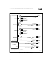
Figure 12-1 shows a block diagram of the DMA unit. The DMA channels are independently con-
figurable. Each channel contains a request input (DREQn) and an acknowledge output
(DMAACKn#). An external peripheral (connected to the DRQn pin) or one of the internal pe-
ripherals (asynchronous serial I/O, synchronous serial I/O, or timer control unit) can request
DMA service. The DMA configuration register is used to select one of the possible sources. In
addition to these hardware request sources, each channel contains a software request register that
can be used to initiate software requests. The channels share an end-of-process signal (EOP#).
This signal functions as either an input or an open-drain output. EOP# either terminates a transfer
(as an input) or signals that a transfer is completed (as an output).


