


Intel386™ EX EMBEDDED MICROPROCESSOR USER’S MANUAL
4-2
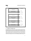
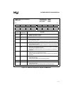
— Power management control registers
— Chip-select unit control registers
— Refresh control unit registers
— Watchdog timer control registers
— Synchronous serial I/O control registers
— Parallel I/O port control registers
4.1.1 Intel386 Processor Core Architecture Registers
These registers are a superset of the 8086 and 80286 processor registers. All 16-bit 8086 and
80286 registers are contained within the 32-bit Intel386 processor core registers. A detailed de-
scription of the Intel386 processor architecture base registers can be found in the Intel386™ SX
Microprocessor Programmer’s Reference Manual (order number 240331).
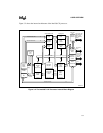
4.1.2 Intel386 EX Processor Peripheral Registers
The Intel386 EX processor contains some peripherals that are common and compatible with the
PC/AT
*
system architecture and others that are useful for embedded applications. The peripheral
registers control access to these peripherals and enable you to configure on-chip system resources
such as timer/counters, power management, chip selects, and watchdog timer.
All peripheral registers reside physically in the expanded I/O address space (addresses 0F000H–
0FFFFH). Peripherals that are compatible with PC/AT system architecture can also be mapped
into DOS I/O address space (addresses 0H–03FFH, 10-bit decode). The following rules apply for
accessing peripheral registers after a system reset:
• Registers within the DOS I/O address space are accessible.
• Registers within the expanded I/O address space are accessible only after the expanded I/O
address space is enabled.
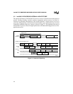
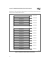
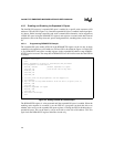
4.2 I/O ADDRESS SPACE FOR PC/AT SYSTEMS
The Intel386 EX processor’s I/O address space is 64 Kbytes. On PC/AT platforms, the DOS op-
erating system and applications assume that only 1 Kbyte of the total 64-Kbyte I/O address space
is used. The first 256 bytes (addresses 00000H–00FFH) are reserved for platform (motherboard)
I/O resources such as the interrupt and DMA controllers, and the remaining 768 bytes (addresses
0100H–03FFH) are available for “general” I/O peripheral card resources. Since only 1 Kbyte of
the address space is supported, add-on I/O peripheral cards typically decode only the lower 10
address lines. Because the upper address lines are not decoded, the 256 platform address locations
and the 768 bus address locations are repeated 64 times (on 1-Kbyte boundaries), covering the
entire 64-Kbyte address space. (See Figure 4-1.)
Generally, add-on I/O peripheral cards do not use the I/O addresses reserved for the platform re-
sources. Software running on the platform can use any of the 64 repetitions of the 256 address
locations reserved for accessing platform resources.