Intel386™ EX EMBEDDED MICROPROCESSOR USER’S MANUAL
15-4
15.2.1 RCU Signals
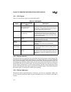
Table 15-1 describes the signals associated with the RCU.
15.2.2 Refresh Intervals
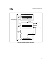
The interval timer unit controls the rate at which the control unit generates refresh requests. Re-
fresh intervals are programmable through the use of a refresh control interval register (RFSCIR)
and a 10-bit down counter. The counter is loaded from RFSCIR, then decremented on each CLK-
OUT falling edge. When the counter reaches one, the interval timer unit reloads the counter from
the RFSCIR and asserts its timeout signal. The timeout signal causes the control unit to initiate a
refresh request, provided there is not one already pending. (The RCU must complete the present
refresh cycle before the control logic can generate a new refresh request). The control unit ignores
the timeout signal if it already has a refresh request pending.
15.2.3 Refresh Addresses
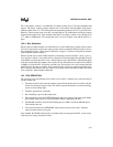
The physical address generated during a refresh bus cycle has two components: address bits
A25:14 (from the refresh base address register) and address bits A13:1 (from the 13-bit address
counter).
Table 15-1. RCU Signals
Signal
Device Pin or Internal
Signal
Description
CLKOUT Device Pin
(from Clock and Power
Management Unit)
Processor Clock:
Provides the clocking signal for the interval counter. The
interval timer unit loads and decrements the counter on
the falling edges of the processor clock.
Timeout Internal signal
(from the interval counter to
the control unit)
Timeout:
Indicates that the interval counter has reached one. The
control unit initiates a refresh request when it detects
this signal, unless a refresh request is pending, in which
case it ignores this signal.
REFRESH# Device pin
(output)
External Refresh:
Indicates that a refresh bus cycle is in progress and that
the refresh address is on the bus.
Refresh
Request
Internal signal Refresh Request:
Indicates that the control unit is requesting bus
ownership.
Refresh
Acknowledge
Internal signal Refresh Acknowledge:
Indicates that the refresh control unit is being granted
bus ownership.
A25:1 Device pins
(output)
Address Bus:
Contains the refresh address during refresh cycles. This
address can be used by the DRAM device to refresh a
single row.


