


Intel386™ EX EMBEDDED MICROPROCESSOR USER’S MANUAL
12-50
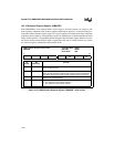
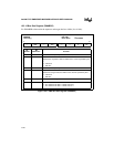
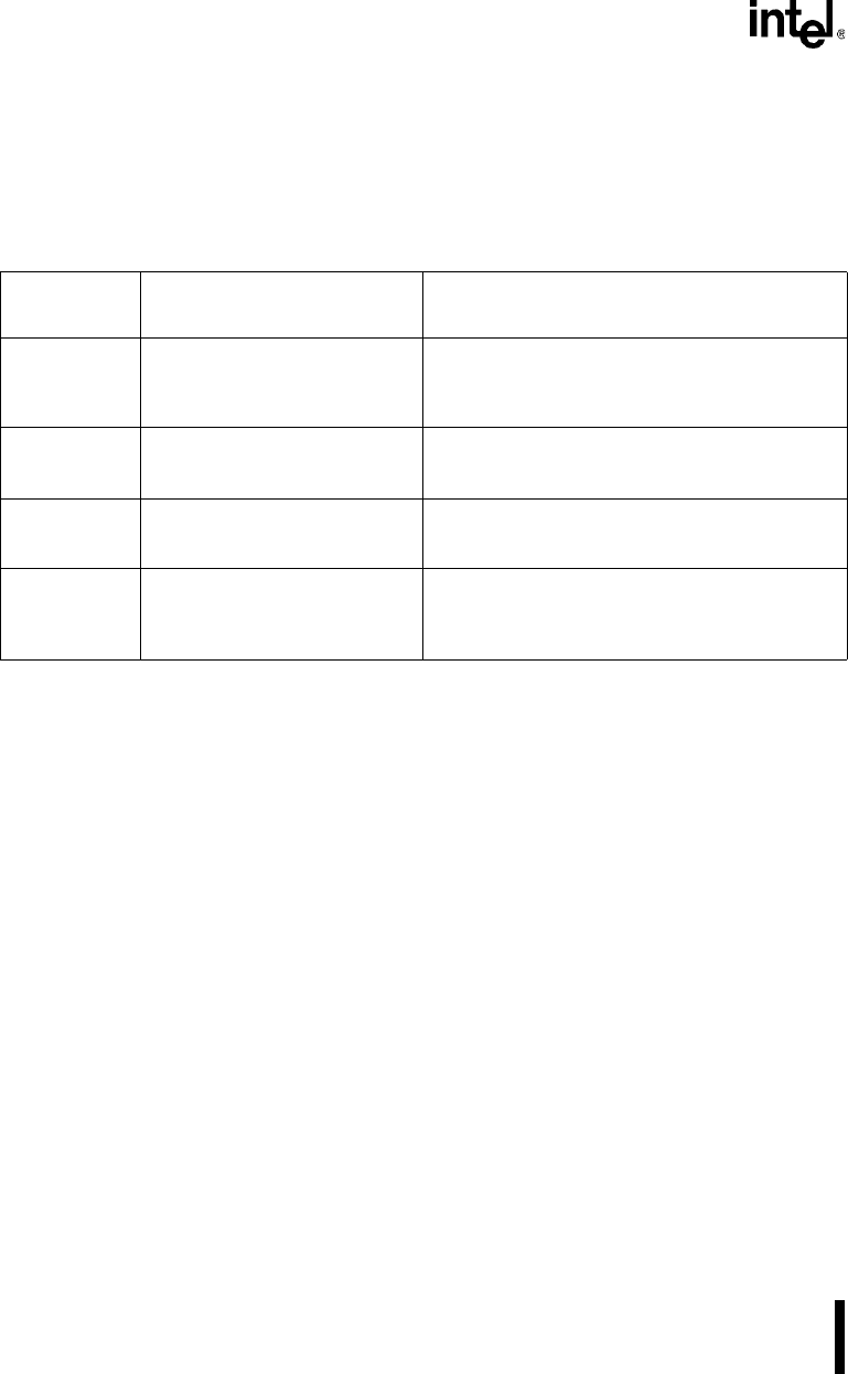
12.3.16 Software Commands
The DMA contains four software commands: clear byte pointer, clear DMA, clear mask register,
and clear transfer complete signal. Each software command has an I/O address associated with it
(see Table 12-4). To issue a software command, write to its I/O address; the data written doesn’t
matter —writing to the location is all that is necessary.
12.4 DESIGN CONSIDERATIONS
EOP# requires an external pull-up resistor. To determine the maximum value, the rise time must
be less than three bus cycles. To determine the minimum value, use the I
OL
specification from the
Intel386™ EX Embedded Microprocessor datasheet (order number 272420).
12.5 PROGRAMMING CONSIDERATIONS
Consider the following when programming the DMA.
• The DMA transfers data between a requester and a target. The transfer direction is
programmable and determines whether the requester or the target is the source or
destination of a transfer.
• The two-cycle data transfer bus cycle option uses a four-byte temporary buffer. During a
buffer transfer, the channel fills the temporary buffer from the source before writing any
data to the destination. Therefore, the number of bus cycles that it takes to transfer data
from the source to the destination depends on the amount of data to transfer and the source
and destination data bus widths.
• Each channel contains a 26-bit requester address, 26-bit target address, and 24-bit byte
count. These values are programmed through the use of 8-bit registers, some of which are
multiplexed at the same addresses. A byte pointer (BP) controls the access to these
multiplexed registers. After you write or read a register that requires a byte pointer
specification, the channel toggles the byte pointer. For example, writing to DMA0TAR0
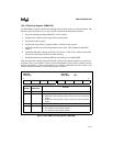
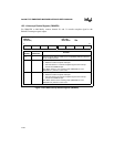
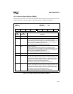
Table 12-4. DMA Software Commands
Name
(Address)
Command Functions
DMACLRBP
(0F00CH or
000CH)
Clear byte pointer Resets the byte pointer flip-flop. Perform this
command at the beginning of any access to the
channel registers, to ensure a predictable place in
the register programming sequence.
DMACLR
(0F00DH or
000DH)
Clear DMA Sets all DMA functions to their default states.
DMACLRMSK
(0F00EH or
000EH)
Clear mask register Simultaneously clears the mask bits of all channels
(enabling all channels).
DMACLRTC
(0F01EH)
Clear transfer complete signal Resets the transfer complete signal (DMAINT).
Allows the source of the DMA request (hardware or
software) to acknowledge the completion of a
transfer process.