Intel386™ EX EMBEDDED MICROPROCESSOR USER’S MANUAL
D-32
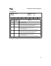
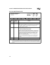
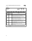
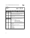
D.29 IER
n
Interrupt Enable
IER0, IER1
(read/write)
Expanded Addr:
ISA Addr:
Reset State:
IER0 IER1
F4F9H F8F9H
03F9H 02F9H
00H 00H
7 0
———— MSRLSTBERBF
Bit
Number
Bit
Mnemonic
Function
7–4 — Reserved; for compatibility with future devices, write zeros to these bits.
3 MS Modem Status Interrupt Enable:
0 = Modem input signal changes do not cause interrupts.
1 = Connects the modem status signal to the interrupt control unit’s
SIOINT
n
output. A change on one or more of the modem input
signals activates the modem status signal.
2 RLS Receiver Line Status Interrupt Enable:
0 = LSR error conditions do not cause interrupts.
1 = Connects the receiver line status signal to the interrupt control unit’s
SIOINT
n
output. Sources for this interrupt include overrun error,
parity error, framing error, and break interrupt.
1 TBE Transmit Buffer Empty Interrupt Enable:
0 = Transmit Buffer Empty signal does not cause interrupts.
1 = Connects the transmit buffer empty signal to the interrupt control
unit’s SIOINT
n
output.
0 RBF Receive Buffer Full Interrupt Enable:
0 = Receive buffer full signal does not cause interrupts.
1 = Connects the receive buffer full signal to the interrupt control unit’s
SIOINT
n
output.
NOTE: The interrupt enable register is multiplexed with the divisor latch high register. You must clear
bit 7 (DLAB) of the serial line control register (LCR
n
) before you can access the interrupt
control register.


