Intel386™ EX EMBEDDED MICROPROCESSOR USER’S MANUAL
9-4
9.2 ICU OPERATION
The following sections describe the ICU operation. The ICU’s interrupt sources, interrupt priority
structure, interrupt vectors, interrupt processing, and polling mode are discussed.
9.2.1 Interrupt Sources
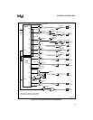
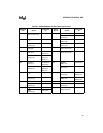
The ICU support a total of 18 interrupt sources (see Table 9-1) but only a maximum of 15 simul-
taneous sources. Eight of these sources are internal peripherals and ten are external device pins
(INT9:0). However, IR3 and IR4 of the master can be connected to either SIOINT1 and SIOINT0
(internal Asynchronous Serial I/O interrupts), or to external device pins INT8 and INT9, respec-
tively. Similarly, IR1 of the slave can be connected to either SSIOINT (internal Synchronous Se-
rial I/O interrupt), or to external device pin INT5. On the slave, the external interrupt signal,
INT6, and the DMA Unit’s DMAINT signal can be swapped before connecting to the slave’s IR4
and IR5 inputs
The device pins (INT3:0) are multiplexed with port pins. When the port pin function (rather than
the interrupt function) is enabled at the pin, V
SS
is internally connected to the ICU’s respective
interrupt request input. The device pins, INT7, INT6, and INT4, must be enabled (using register
bits) in order to be used. The port 3 configuration register (P3CFG) controls INT3:0 interrupt
source connections, and the interrupt configuration register (INTCFG) controls the INT9:4 inter-
rupt source connections. The modem control registers (MCR1 and MCR0) are also used to con-
trol the INT9:8 interrupt source connections.


