17-3
WATCHDOG TIMER UNIT
17.1.1 WDT Signals
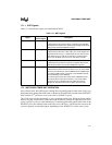
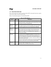
Table 17-1 describes the signals associated with the WDT.
17.2 WATCHDOG TIMER UNIT OPERATION
After a device reset, the WDT begins counting down in general-purpose timer mode. Unless you
change the mode, change the reload value, or disable it, the WDT times out and asserts WDTOUT
after 4 million (2
22
) processor clock cycles (PH1 or CLKOUT cycles).
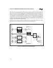
The 32-bit down-counter decrements on every processor clock cycle. When the down-counter
reaches zero, the 8-state binary counter drives the WDTOUT pin high for eight processor clock
cycles (16 CLK2 cycles) to signal the timeout. An internal signal carries the inverted value of the
WDTOUT pin to the interrupt control unit (the slave’s IR7 line). A WDT timeout can reset the
system or generate an interrupt request, depending on how WDTOUT is used in your system.
Table 17-1. WDT Signals
Signal
Device Pin or
Internal Signal
Description
ADS# Device pin Address Status (from the bus interface unit):
Indicates that the processor is driving a valid bus-cycle definition
and address onto its pins. Bus monitor mode reloads and starts the
down-counter each time ADS# is asserted.
IDLE Internal signal Idle (from the clock and power management unit):
Indicates that the device is in idle mode (core clocks stopped and
peripheral clocks running). In watchdog mode, the down-counter
stops when the core is idle. In bus monitor or general-purpose
timer mode, the WDT continues to run while the core is idle.
READY# Device pin Ready (from the bus interface unit):
Indicates that the current bus cycle has completed. Bus monitor
mode stops the down-counter when READY# is asserted.
WDTOUT Device pin Watchdog Timer Output:
Indicates that the down-counter has timed out. If you want a WDT
timeout to reset the device, connect WDTOUT to the RESET input.
If you want a WDT timeout to generate a nonmaskable interrupt,
connect WDTOUT to the NMI input.
An internal signal carries the inverted value of WDTOUT to the
interrupt control unit (the slave’s IR7 line). If you want a WDT
timeout to cause a maskable interrupt, enable the interrupt.
(Chapter 8, “Interrupt Control Unit,” explains how to do this.)


