14-1
CHAPTER 14
CHIP-SELECT UNIT
The Chip-select Unit (CSU) of the processor can be used to eliminate external address and bus-
cycle decoders in your system. The chip-selects generated by this unit can simplify external “glue
logic” by providing signals that can be connected directly to the chip-enable inputs of external
memory and I/O devices. If a particular device or address region does not require a chip-enable
signal, a chip-select region can be programmed only to enable termination of accesses to that
region. A chip-select region can also be programmed to generate a chip-enable signal and
terminate accesses to that region.
The chip-select unit provides eight signals, or channels, allowing direct access to up to eight de-
vices or address regions. You can individually configure the channels for compatibility with a va-
riety of devices. Each channel can operate in either 16-bit or 8-bit bus mode, generate up to 31
wait states, and either terminate a bus cycle automatically or wait for an external ready signal.
This chapter is organized as follows:
• Overview (see below)
• CSU Operation (page 14-2)
• Register Definitions (page 14-13)
• Design Considerations (page 14-21)
• Programming Considerations (page 14-22)
14.1 OVERVIEW
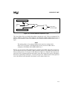
Each chip-select channel consists of address and mask registers and an output signal. The address
and mask registers allow you to define memory or I/O address blocks for each channel. You also
specify whether or not the chip-select is activated when the processor is operating in system man-
agement mode. When the processor accesses a channel’s address block, the CSU activates the
channel’s output signal. Connecting a channel’s output to a memory or I/O device simplifies
memory and I/O interfacing by removing the need for and delay of decoding addresses externally.
NOTE
Chip-select channels are not activated during interrupt acknowledge cycles
and halt and shutdown cycles.


