9-15
INTERRUPT CONTROL UNIT
configuring more than six external 82C59As. Since the polling mode doesn’t require that the ad-
ditional 82C59As be cascaded from the master, the number of interrupt request sources for a
polled system is limited only by the number of 82C59As that the system can address.
Polling and standard interrupt processing can be used within the same program. Systems that use
polling as the only method of device servicing must still fully initialize the 82C59A modules. Al-
so, the interrupt requests to the core must be disabled using the mask bits or the CLI instruction.
9.3 REGISTER DEFINITIONS
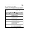
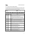
The registers associated with the ICU consist of pin and signal configuration registers, initializa-
tion command words (ICWs), operation command words (OCWs), and status registers.
• The configuration registers enable the external interrupt sources.
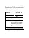
• The ICWs initialize the 82C59As during system initialization.
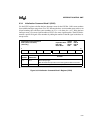
• The OCWs modify an 82C59A’s operation during program execution.
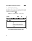
• The status registers reflect pending and in-service interrupts.
NOTE
ICW2, ICW3 and ICW4 of an 82C59A are all at the same address. Therefore a
programming sequence must be followed to program these registers. The first
access goes to ICW2, the second to ICW3 and the third to ICW4. When
programming any of these registers, the above sequence must be followed and
completed every time.
When initializing the ICU, write first to ICW1, then to ICW2, ICW3 and
ICW4 in order.
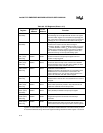
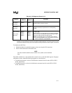
Table 9-2 describes these registers and the following sections contain bit descriptions for each
register.


