


Intel386™ EX EMBEDDED MICROPROCESSOR USER’S MANUAL
11-16
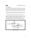
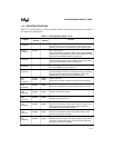
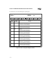
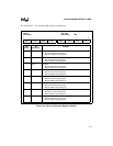
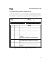
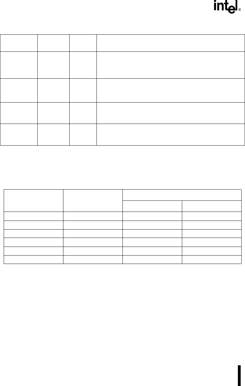
For PC compatibility, the SIO unit accesses its 11 registers through 8 I/O addresses. The RBRn,
TBRn, and DLLn registers share the same addresses and the IERn and DLHn registers share the
same addresses. Bit 7 (DLAB) of the LCRn determines which register is accessed during a read
or write operation (Table 11-6).
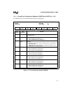
IIR0
IIR1
(read only)
0F4FAH
0F8FAH
03FAH
02FAH
Interrupt ID:
Indicates whether the modem status, transmit buffer empty,
receive buffer full, or receiver line status signal generated an
interrupt request.
MCR0
MCR1
(read/write)
0F4FCH
0F8FCH
03FCH
02FCH
Modem Control:
Controls the interface with the modem or data set.
Allows use of external UARTs.
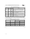
MSR0
MSR1
(read/write)
0F4FEH
0F8FEH
03FEH
02FEH
Modem Status:
Provides the current state of the control lines for the modem or
data set to the CPU.
SCR0
SCR1
(read/write)
0F4FFH
0F8FFH
03FFH
02FFH
Scratch Pad:
An 8-bit read/write register available for use as a scratch pad; has
no effect on SIO
n
operation.
Table 11-6. Access to Multiplexed Registers
Expanded Address PC/AT Address
Register Accessed
DLAB = 0 DLAB = 1
0F4F8H (read) 03F8H (read) RBR0 DLL0
0F4F8H (write) 03F8H (write) TBR0 DLL0
0F4F9H (read/write) 03F9H (read/write) IER0 DLH0
0F8F8H (read) 02F8H (read) RBR1 DLL1
0F8F8H (write) 02F8H (write) TBR1 DLL1
0F8F9H (read/write) 02F9H (read/write) IER1 DLH1
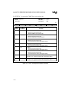
Table 11-5. SIO Registers (Sheet 2 of 2)
Register
Expanded
Address
PC/AT*
Address
Function