12-39
DMA CONTROLLER
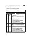
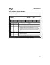
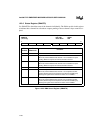
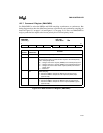
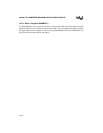
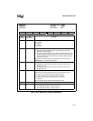
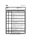
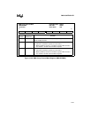
Figure 12-25. DMA Mode 1 Register (DMAMOD1)
DMA Mode 1
DMAMOD1
(write only)
Expanded Addr:
ISA Addr:
Reset State:
F00BH
000BH
00H
7 0
DTM1 DTM0 TI AI TD1 TD0 0 CS
Bit
Number
Bit
Mnemonic
Function
7–6 DTM1:0 Data-transfer Mode:
00 = Demand
01 = Single
10 = Block
11 = Cascade
5 TI Target Increment/Decrement:
0 = Causes the target address to be incremented after each data
transfer in a buffer transfer.
1 = Causes the target address for the channel specified by bit 0 to be
decremented after each data transfer in a buffer transfer. Note that it
does not decrement words. When decrementing it will do two byte
transfers for a word.
Note: When the target address is programmed to remain constant
(DMAMOD2.2 = 1), this bit is a don’t care.
4 AI Autoinitialize:
0 = Disables the autoinitialize buffer-transfer mode for the channel
specified by bit 0.
1 = Enables the autoinitialize buffer-transfer mode for the channel
specified by bit 0.
3–2 TD1:0 Transfer Direction:
Determines the transfer direction for the channel specified by bit 0.
00 = Target is read; nothing is written (used for testing)
01 = Data is transferred from the requester to the target
10 = Data is transferred from the target to the requester
11 = Reserved
Note: In cascade mode, these bits become don’t cares.
1 0 Must be 0 for correct operation.
0 CS Channel Select:
0 = The selections for bits 7–2 affect channel 0.
1 = The selections for bits 7–2 affect channel 1.


